netquirks
Exploring the quirks of Network Engineering
Routing loop shambles
Hey everyone! It’s been a while since I posted anything, but I’ve come across this interesting quirk in my studies which I think would be of interest for anyone studying OSPF, BGP and how they work together. Comments and thoughts are welcome as always.
This blog introduces the concept of OSPF sham-links and how they can be used to influence OSPF routes across an MPLS core. It also explores how, if not used carefully, routing loops could occur with disastrous effects.
As a reminder, once I’ve set up the scenario, I’ll go through the quirk (explaining the problem), the search (finding a solution) and the work (implementing the solution) as usual.
Scenario
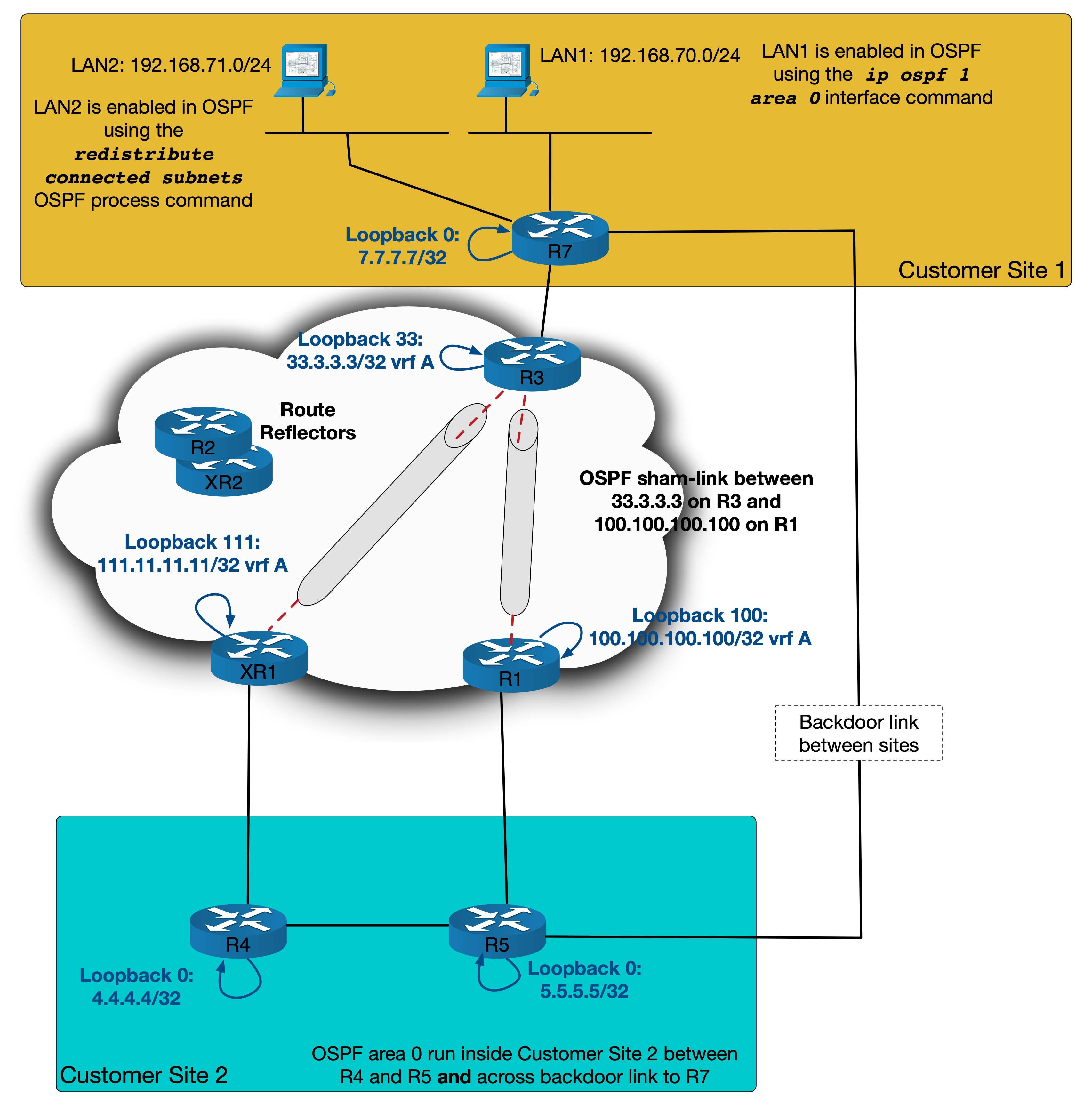
This scenario looks at a standard MPLS customer with two sites. These sites use OSPF as the PE-CE routing protocol and have a backdoor link between them over which OSPF is run – joining both sites into area 0.
The diagram looks like this:

I’ve labbed this in GNS3 and all routers are IOS-XE devices except for XR1 and XR2 which, as the names suggest, are IOS-XR boxes.
LAN ranges have been simulated using loopbacks. Each PE is doing redistribution from OSPF into MP-BGP (internal, external 1 and external 2) and from MP-BGP into OSPF.
The design goal here is to have both sites connected in OSPF area 0 using the backdoor link as a backup – with traffic normally preferring to go over the MPLS network (or OSPF super backbone). XR1 and R1 should back each other up. Only if both of these are down should traffic traverse the backdoor link.
I’ll first introduce the problems inherent in the default behaviour as shown in the diagram above – focusing on how R4 and R5 would reach LAN1 (192.168.70.0/24) on R7. I’ll then go into how a sham-link can help solve these problems. However, as we will see in the quirk, if sham-links aren’t applied correctly some problems could appear.
OSPF and MPLS
We’ll start by looking at how OSPF and MPLS interact. For now, let’s assume the backdoor link is shutdown.
OSPF is being used between the PEs and CEs. So the PEs find themselves redistributing from OSPF into MP-BGP. When this is done, MP-BGP will set these OSPF specific community/values into the resulting VPNv4 prefix:
- The domain ID – this is an extended community taken from the process ID on the router and is considered when redistributing back into OSPF (more on that below).
- The route-type – an extended community broken up into 3 parts: the area, the LSA type and an additional option.
- The OSPF router id – another extended community representing the router sourcing this VPNv4 prefix.
- The OSPF cost is copied to the MED value.
Here we can see the output from R3 as it has redistributed the OSPF route for LAN 1 into BGP:
R3#sh run | sec router ospf
router ospf 1 vrf A
 router-id 3.3.3.3
 redistribute bgp 1 subnets
 network 10.3.7.3 0.0.0.0 area 0
R3#sh bgp vpnv4 unicast vrf A 192.168.70.0
BGP routing table entry for 1:1:192.168.70.0/24, version 77
Paths: (1 available, best #1, table A)
  Advertised to update-groups:
     1
  Refresh Epoch 1
  Local
    10.3.7.7 (via vrf A) from 0.0.0.0 (3.3.3.3)
      Origin incomplete, metric 2, localpref 100, weight 32768,
        valid, sourced, best
      Extended Community: RT:100:100
              OSPF DOMAIN ID:0x0005:0x000000010200
        OSPF RT:0.0.0.0:2:0 OSPF ROUTER ID:3.3.3.3:0
      mpls labels in/out 24/nolabel
      rx pathid: 0, tx pathid: 0x0
R3#
You can see the Domain ID field is set to 0x0005:0x000000010200. The 00000001 section represents process ID 1. MED is 2 – this represents the OSPF cost of 2 to reach LAN1. The RT is 0.0.0.0:2:0 and router-ID is 3.3.3.3:0.
NB. IOS-XR doesn’t encode the domain ID by default. For this scenario we will assume it has been configured on XR1 using the following commands:
RP/0/RP0/CPU0:XR1(config)#router ospf 1
RP/0/RP0/CPU0:XR1(config-ospf)# vrf A
RP/0/RP0/CPU0:XR1(config-ospf-vrf)# domain-id type 0005 value 000000010200
What’s important to consider here is how the PEs on the other end of the MPLS network redistribute this back into OSPF on the other side.
When the MP-BGP prefix is redistributed back into OSPF by either R1 or XR1, it uses the domain ID to determine if the route should appear as inter-area or external (I’m using colour coding here to help with differentiating between area descriptions… and because trying to read inter and intra when they occur in the same sentence makes my head hurt). If the Process ID section of the Domain ID in the VPNv4 prefix matches the local OSPF process ID on the PE doing the redistribution, then the prefix will be sent into OSPF using an inter-area Type 3 LSA. If it doesn’t, it will be an external Type 5 LSA.
In our setup, the Domain ID and Process ID all match – so when R4 and R5 receive the Type 3 LSA they see it as inter-area:
R4#sh ip route 192.168.70.0
Routing entry for 192.168.70.0/24
  Known via "ospf 1", distance 110, metric 3, type inter area
  Last update from 10.4.11.11 on GigabitEthernet1.411, 00:01:13 ago
  Routing Descriptor Blocks:
  * 10.4.11.11, from 11.11.11.11, 00:01:13 ago, via GigabitEthernet1.411
      Route metric is 3, traffic share count is 1
R4#sh ip ospf database summary 192.168.70.0

            OSPF Router with ID (4.4.4.4) (Process ID 1)

                Summary Net Link States (Area 0)

  LS age: 86
  Options: (No TOS-capability, DC, Downward)
  LS Type: Summary Links(Network)
  Link State ID: 192.168.70.0 (summary Network Number)
  Advertising Router: 1.1.1.1
  LS Seq Number: 80000001
  Checksum: 0x36CF
  Length: 28
  Network Mask: /24
        MTID: 0         Metric: 2

  LS age: 86
  Options: (No TOS-capability, DC, Downward)
  LS Type: Summary Links(Network)
  Link State ID: 192.168.70.0 (summary Network Number)
  Advertising Router: 11.11.11.11
  LS Seq Number: 80000001
  Checksum: 0x9D4
  Length: 28
  Network Mask: /24
        MTID: 0         Metric: 2

R4#
This all looks well and good. It’s worth pointing out here, that OSPF has a preference for which path to select based on the route types. The order of preference is as follows*:
- Intra-Area (O)
- Inter-Area (O IA)
- External Type 1 (E1)
- NSSA Type 1 (N1)
- External Type 2 (E2)
- NSSA Type 2 (N2)
(* This is for Cisco IOS software older than 15.1(2)S. During and after 15.1(2)S sees the E and N orders reversed. This isn’t relevant to this blog but worth noting)
It doesn’t matter what the OSPF cost is. If OSPF has the option of an intra-area route over an inter-area or external route, it will pick the intra-area option every time. Keeping that in mind, let’s bring up the backdoor link and see what happens…
The backdoor link
You might already be able to predict that as soon as we bring up the backdoor link, R4 and R5 will immediately see LAN1 as an intra-area route:
R5#conf t
Enter configuration commands, one per line.  End with CNTL/Z.
R5(config)#
%SYS-5-CONFIG_I: Configured from console by console
R5(config)#interface gi1.57
R5(config-subif)#no shut
R5(config-subif)#
%OSPF-5-ADJCHG: Process 1, Nbr 7.7.7.7 on GigabitEthernet1.57 from DOWN to INIT,
  Received Hello
%OSPF-5-ADJCHG: Process 1, Nbr 7.7.7.7 on GigabitEthernet1.57 from INIT to 2WAY,
 2-Way Received
%OSPF-5-ADJCHG: Process 1, Nbr 7.7.7.7 on GigabitEthernet1.57 from 2WAY to EXSTART,
 AdjOK?
R5(config-subif)#
%OSPF-5-ADJCHG: Process 1, Nbr 7.7.7.7 on GigabitEthernet1.57 from EXSTART to
 EXCHANGE, Negotiation Done
%OSPF-5-ADJCHG: Process 1, Nbr 7.7.7.7 on GigabitEthernet1.57 from EXCHANGE to
 LOADING, Exchange Done
%OSPF-5-ADJCHG: Process 1, Nbr 7.7.7.7 on GigabitEthernet1.57 from LOADING to FULL,
 Loading Done
R5(config-subif)#do sh ip route 192.168.70.0
Routing entry for 192.168.70.0/24
  Known via "ospf 1", distance 110, metric 101, type intra area
  Last update from 10.5.7.7 on GigabitEthernet1.57, 00:00:17 ago
  Routing Descriptor Blocks:
  * 10.5.7.7, from 7.7.7.7, 00:00:17 ago, via GigabitEthernet1.57
      Route metric is 101, traffic share count is 1
R5(config-subif)#
R5(config-subif)#do sh ip ospf database router 7.7.7.7

            OSPF Router with ID (5.5.5.5) (Process ID 1)

                Router Link States (Area 0)

  LS age: 37
  Options: (No TOS-capability, DC)
  LS Type: Router Links
  Link State ID: 7.7.7.7
  Advertising Router: 7.7.7.7
  LS Seq Number: 800000C1
  Checksum: 0x840E
  Length: 60
  AS Boundary Router
  Number of Links: 3

    Link connected to: a Stub Network
     (Link ID) Network/subnet number: 192.168.70.0
     (Link Data) Network Mask: 255.255.255.0
      Number of MTID metrics: 0
       TOS 0 Metrics: 1

    Link connected to: a Transit Network
     (Link ID) Designated Router address: 10.5.7.7
     (Link Data) Router Interface address: 10.5.7.7
      Number of MTID metrics: 0
       TOS 0 Metrics: 100

    Link connected to: a Transit Network
     (Link ID) Designated Router address: 10.3.7.7
     (Link Data) Router Interface address: 10.3.7.7
      Number of MTID metrics: 0
       TOS 0 Metrics: 1

R5(config-subif)#
You may also have spotted that the previous Type 3 LSA is no longer present. This is because the PE routers that were doing the redistribution from MP-BGP now prefer the local OSPF path. MP-BGP (iBGP from the reflectors in this case) has an administrative distance of 200. OSPF has an administrative distance of 110. OSPF wins and since redistribution takes place from the RIB, there are no MP-BGP routes to redistribute into OSPF:
R4#sh ip ospf database summary 192.168.70.0

            OSPF Router with ID (4.4.4.4) (Process ID 1)
R4#
R1#sh ip route vrf A 192.168.70.0

Routing Table: A
Routing entry for 192.168.70.0/24
  Known via "ospf 1", distance 110, metric 102, type intra area
  Redistributing via bgp 1
  Advertised by bgp 1 match internal external 1 & 2
  Last update from 10.1.5.5 on GigabitEthernet1.15, 00:04:30 ago
  Routing Descriptor Blocks:
  * 10.1.5.5, from 7.7.7.7, 00:04:30 ago, via GigabitEthernet1.15
      Route metric is 102, traffic share count is 1
R1#
Now you might be asking why I bothered to outline the difference between the PE redistributing the BGP prefix as inter-area versus external, if the R4 and R5 are just going to pick the intra-area route regardless. Well this becomes relevant when we consider how we are going to make the MPLS core the preferred path to reach LAN1.
As it stands at the moment, no matter how high we set the metric on the link between R5 and R7, traffic from Site 2 to LAN1 will always go over the backdoor link. In short, we need a way to make an intra-area route appear over the MPLS core. Here’s were sham-links come in.
Sham-Links
A sham-link is similar to an OSPF Virtual-Link but it can be run as any area and is designed for just these types of scenarios. Essentially, the PEs at either end establish an OSPF neighborship and consider themselves to be directly connected within the same area. This will all allow Type 1 and Type 2 LSAs to appear over MPLS – simulating a point-to-point connection between PEs. Let’s look at how this is setup…
Each PE creates a new loopback and puts it into vrf A. The sham-link is configured between these loopbacks.
Here’s the diagram and config for the setup:

R3#conf t
Enter configuration commands, one per line.  End with CNTL/Z.
R3(config)#interface Loopback33
R3(config-if)#vrf forwarding A
R3(config-if)#ip address 33.3.3.3 255.255.255.255
R3(config-if)#exit
R3(config)#router ospf 1 vrf A
R3(config-router)#area 0 sham-link 33.3.3.3 111.11.11.11
R3(config-router)#exit
R3(config)#router bgp 1
R3(config-router)#address-family ipv4 vrf A
R3(config-router-af)#network 33.3.3.3 mask 255.255.255.255
RP/0/RP0/CPU0:XR1#conf
RP/0/RP0/CPU0:XR1(config)#interface Loopback111
RP/0/RP0/CPU0:XR1(config-if)#vrf A
RP/0/RP0/CPU0:XR1(config-if)#ipv4 address 111.11.11.11/32
RP/0/RP0/CPU0:XR1(config-if)#root
RP/0/RP0/CPU0:XR1(config)#router ospf 1
RP/0/RP0/CPU0:XR1(config-ospf)#vrf A
RP/0/RP0/CPU0:XR1(config-ospf-vrf)#address-family ipv4 unicast
RP/0/RP0/CPU0:XR1(config-ospf-vrf)#area 0
RP/0/RP0/CPU0:XR1(config-ospf-vrf-ar)#sham-link 111.11.11.11 33.3.3.3
RP/0/RP0/CPU0:XR1(config-ospf-vrf-ar)#root
RP/0/RP0/CPU0:XR1(config)#router bgp 1
RP/0/RP0/CPU0:XR1(config-bgp)#vrf A
RP/0/RP0/CPU0:XR1(config-bgp-vrf)#rd 1:1
RP/0/RP0/CPU0:XR1(config-bgp-vrf)#address-family ipv4 unicast
RP/0/RP0/CPU0:XR1(config-bgp-vrf-af)#network 111.11.11.11/32
Now it’s important to pause there and highlight a key requirement: We need to make sure that each PE has reachability to the others sham-link loopback over MPLS but not over OSPF. To that end, we should not enable OSPF on the PEs new loopbacks.
But why is this?
To answer this, consider how R3 learns about 111.11.11.11/32. If XR1 were to enable OSPF on this loopback, it would include it as a connected network in its Type 1 LSA. This would be then be communicated throughout the OSPF area, across the backdoor link and arrive at R3. All devices are in the same area so their view of the LSDB would be the same. Assuming loopback111 is also redistributed into BGP, R3 would now have two options to reach it – one via OSPF with administrative distance or 110 and one via iBGP with an administrative distance of 200.

OSPF would naturally win and the sham-link would be built over the backdoor link, which defeats the very goal we are trying to achieve! As such, we have to make sure that OSPF is not enabled on loopback 111 or loopback 33.
But, I hear you ask, what if we are still redistributing from MP-BGP into OSPF? Won’t R3 still see the path to loopback 111 via an external Type 5 LSA, which will still have a lower AD than iBGP’s 200?
Well, yes, but OSPF has a loop prevention mechanism built into it to prevent just such a thing…
When an LSA is created from redistributing from MP-BGP to OSPF, an OSPF feature called the down-bit is set in the resulting LSA. The down-bit ensures that any prefixes that are redistributed from MP-BGP into OSPF are not then redistributed back into MP-BGP. So whist R3 will see the Type 5 LSA in its LSDB it will not consider it as a valid route since it is already getting the prefix via MP-BGP and the down-bit indicates that it came from MP-BGP.

Here is the LSA as seen in the LSDB.
R5#sh ip ospf database external 111.11.11.11

            OSPF Router with ID (5.5.5.5) (Process ID 1)

                Type-5 AS External Link States

  LS age: 881
  Options: (No TOS-capability, DC, Downward)
  LS Type: AS External Link
  Link State ID: 111.11.11.11 (External Network Number )
  Advertising Router: 1.1.1.1
  LS Seq Number: 8000004D
  Checksum: 0x245C
  Length: 36
  Network Mask: /32
        Metric Type: 2 (Larger than any link state path)
        MTID: 0
        Metric: 1
        Forward Address: 0.0.0.0
        External Route Tag: 3489660929

  LS age: 1998
  Options: (No TOS-capability, DC, Downward)
  LS Type: AS External Link
  Link State ID: 111.11.11.11 (External Network Number )
  Advertising Router: 3.3.3.3
  LS Seq Number: 80000055
  Checksum: 0xD798
  Length: 36
  Network Mask: /32
        Metric Type: 2 (Larger than any link state path)
        MTID: 0
        Metric: 1
        Forward Address: 0.0.0.0
        External Route Tag: 3489660929

R5#
And if we check, we find that R3’s best path is via MP-BGP.
R3#sh ip route vrf A 111.11.11.11

Routing Table: A
Routing entry for 111.11.11.11/32
  Known via "bgp 1", distance 200, metric 0, type internal
  Redistributing via ospf 1
  Advertised by ospf 1 subnets
  Last update from 11.11.11.11 19:34:53 ago
  Routing Descriptor Blocks:
  * 11.11.11.11 (default), from 2.2.2.2, 19:34:53 ago
      Route metric is 0, traffic share count is 1
      AS Hops 0
      MPLS label: 24018
      MPLS Flags: MPLS Required
R3#
This loop prevention mechanism isn’t crucial to understanding the operation of the sham-link but it will come into play later on when we look at a potential routing loop.
Getting back to the sham-link, once we configure everything as outlined above the link comes up:
RP/0/RP0/CPU0:XR1#sh ospf vrf A sham-links

Sham Links for OSPF 1, VRF A

Sham Link OSPF_SL0 to address 33.3.3.3 is up
Area 0, source address 111.11.11.11
IfIndex = 1
  Run as demand circuit
  DoNotAge LSA allowed., Cost of using 1
  Transmit Delay is 1 sec, State POINT_TO_POINT,
  Timer intervals configured, Hello 10, Dead 40, Wait 40, Retransmit 5
    Hello due in 00:00:06:794
    Adjacency State FULL (Hello suppressed)
    Number of DBD retrans during last exchange 0
    Index 2/2, retransmission queue length 0, number of retransmission 0
    First 0(0)/0(0) Next 0(0)/0(0)
    Last retransmission scan length is 0, maximum is 0
    Last retransmission scan time is 0 msec, maximum is 0 msec
RP/0/RP0/CPU0:XR1#sh ospf vrf A neighbor

* Indicates MADJ interface
# Indicates Neighbor awaiting BFD session up

Neighbors for OSPF 1, VRF A

Neighbor ID     Pri   State           Dead Time   Address         Interface
3.3.3.3         1     FULL/  -           -        33.3.3.3        OSPF_SL0
    Neighbor is up for 00:01:20
4.4.4.4         1     FULL/BDR        00:00:39    10.4.11.4       Gi0/0/0/0.411
    Neighbor is up for 19:32:22

Total neighbor count: 2
RP/0/RP0/CPU0:XR1#
R3#sh ip ospf sham-links
Sham Link OSPF_SL8 to address 111.11.11.11 is up
Area 0 source address 33.3.3.3
  Run as demand circuit
  DoNotAge LSA allowed. Cost of using 1 State POINT_TO_POINT,
  Timer intervals configured, Hello 10, Dead 40, Wait 40,
    Hello due in 00:00:07
    Adjacency State FULL (Hello suppressed)
    Index 1/2/2, retransmission queue length 0, number of retransmission 0
    First 0x0(0)/0x0(0)/0x0(0) Next 0x0(0)/0x0(0)/0x0(0)
    Last retransmission scan length is 0, maximum is 0
    Last retransmission scan time is 0 msec, maximum is 0 msec
R3#
Both routers establish an OSPF adjacency and see each other as connected over a point-to-point link:
RP/0/RP0/CPU0:XR1#sh ospf vrf A database router 11.11.11.11
Thu Oct  3 12:31:10.478 UTC

            OSPF Router with ID (11.11.11.11) (Process ID 1, VRF A)

                Router Link States (Area 0)

  LS age: 151
  Options: (No TOS-capability, DC)
  LS Type: Router Links
  Link State ID: 11.11.11.11
  Advertising Router: 11.11.11.11
  LS Seq Number: 800000ef
  Checksum: 0xc78
  Length: 48
  Area Border Router
  AS Boundary Router
   Number of Links: 2

    Link connected to: another Router (point-to-point)
     (Link ID) Neighboring Router ID: 3.3.3.3
     (Link Data) Router Interface address: 0.0.0.1
      Number of TOS metrics: 0
       TOS 0 Metrics: 1

    Link connected to: a Transit Network
     (Link ID) Designated Router address: 10.4.11.11
     (Link Data) Router Interface address: 10.4.11.11
      Number of TOS metrics: 0
       TOS 0 Metrics: 1

RP/0/RP0/CPU0:XR1#
What’s interesting here is how XR1 sees the path to LAN1 over the sham-link:
RP/0/RP0/CPU0:XR1#sh route vrf A ipv4 192.168.70.0/24
Thu Oct  3 12:31:43.212 UTC

Routing entry for 192.168.70.0/24
  Known via "bgp 1", distance 200, metric 2, type internal
  Installed Oct  3 12:28:40.433 for 00:03:04
  Routing Descriptor Blocks
    3.3.3.3, from 2.2.2.2
     Nexthop in Vrf: "default", Table: "default", IPv4 Unicast, Table Id:0xe0000000
     Route metric is 2
  No advertising protos.
RP/0/RP0/CPU0:XR1#
It sees it as a BGP route and not an OSPF route! If we look at its BGP entry we see this:
RP/0/RP0/CPU0:XR1#sh bgp vpnv4 unicast vrf A 192.168.70.0
Thu Oct  3 12:32:15.246 UTC
BGP routing table entry for 192.168.70.0/24,Route Distinguisher: 1:1
Versions:
  Process           bRIB/RIB  SendTblVer
  Speaker                462         462
Last Modified: Oct  3 12:28:40.387 for 00:03:37
Paths: (2 available, best #1)
  Not advertised to any peer
  Path #1: Received by speaker 0
  Not advertised to any peer
  Local
    3.3.3.3 (metric 20) from 2.2.2.2 (3.3.3.3)
      Received Label 24
      Origin incomplete, metric 2, localpref 100, valid, internal, best,
          group-best, import-candidate, imported
      Received Path ID 0, Local Path ID 1, version 462
      Extended community: OSPF domain-id:0x5:0x000000010200
         OSPF route-type:0:2:0x0 OSPF router-id:3.3.3.3 RT:100:100
      Originator: 3.3.3.3, Cluster list: 2.2.2.2
      Source AFI: VPNv4 Unicast, Source VRF: A, Source Route Distinguisher: 1:1
  Path #2: Received by speaker 0
  Not advertised to any peer
  Local
    3.3.3.3 (metric 20) from 12.12.12.12 (3.3.3.3)
      Received Label 24
      Origin incomplete, metric 2, localpref 100, valid, internal,
        import-candidate, imported
      Received Path ID 0, Local Path ID 0, version 0
      Extended community: OSPF domain-id:0x5:0x000000010200
         OSPF route-type:0:2:0x0 OSPF router-id:3.3.3.3 RT:100:100
      Originator: 3.3.3.3, Cluster list: 12.12.12.12
      Source AFI: VPNv4 Unicast, Source VRF: A, Source Route Distinguisher: 1:1
RP/0/RP0/CPU0:XR1#
It is clearly an OSPF based route. The OSPF attributes are all present. But how can an OSPF path over the sham-link appear as a BGP route?
Remember that in order to send traffic across the MPLS core two labels will be needed. The top label represents the next-hop PE. This will typically be repeatedly swapped as the packet crosses the core (unless we’re using segment routing but that’s a whole other story). The second and bottom label is the VPN label used to represent this customers prefix or VRF. This label is needed since the core P routers won’t know anything of the customer subnets. This label is communicated in the VPNv4 update from R3 as it redistributes LAN1 into MP-BGP.
Here is the logical process that XR1 is follows:
- XR1 runs the Dijkstra algorithm to find LAN1, taking the sham-link into account as a point-to-point link.
- If the sham-link wins, XR1 will then use a VPNv4 route for LAN1, which in this case is being redistributed by R3. The best VPNv4 route will be used and placed in the BGP RIB instead of an OSPF route.
This is logic is due to the recursion that is taking place over the sham-link:
RP/0/RP0/CPU0:XR1#show cef vrf A 192.168.70.0
Thu Oct  3 12:41:27.680 UTC
192.168.70.0/24, version 679, internal 0x5000001 0x0 (ptr 0xdf126ec) [1], 0x0
  (0xe0d88e8), 0xa08 (0xe4dc4e8)
 Updated Oct  3 12:28:40.444
 Prefix Len 24, traffic index 0, precedence n/a, priority 3
   via 3.3.3.3/32, 3 dependencies, recursive [flags 0x6000]
    path-idx 0 NHID 0x0 [0xd67f4f0 0x0]
    recursion-via-/32
    next hop VRF - 'default', table - 0xe0000000
    next hop 3.3.3.3/32 via 24001/0/21
     next hop 10.2.11.2/32 Gi0/0/0/0.211 labels imposed {16 24}
     next hop 10.11.12.12/32 Gi0/0/0/0.1112 labels imposed {24000 24}
RP/0/RP0/CPU0:XR1#
So R3’s redistribution of LAN1 is needed so that XR1 has a VPN label to send traffic across the MPLS core. Here label 24 is the VPN label assigned by R3 and 16 and 24000 are the transport labels for the next hop of R3 via ECMP through Gi0/0/0/0.211 and Gi0/0/0/0.1112 respectively.
If we verify the source of the VPN label we can see that R3 is indeed assigning label 24:
R3#sh mpls forwarding-table vrf A
Local      Outgoing   Prefix           Bytes Label   Outgoing   Next Hop
Label      Label      or Tunnel Id     Switched      interface
24         No Label   192.168.70.0/24[V]   \
                                       0             Gi1.37     10.3.7.7
31         Pop Label  33.3.3.3/32[V]   0             aggregate/A
34         No Label   10.3.7.0/24[V]   0             aggregate/A
41         No Label   7.7.7.7/32[V]    0             Gi1.37     10.3.7.7
48         No Label   10.5.7.0/24[V]   0             Gi1.37     10.3.7.7
R3#
As a side note, remember that the MP-BGP prefix that XR1 recursively uses is still in competition with any other VPNv4 route to the same destination (this becomes important later).
As a result of all of this, XR1 will not redistribute any OSPF routes into MP-BGP that it prefers over the sham-link. Redistribution takes place from the global RIB (or vrf RIB in this case) and there is no OSPF prefix in the RIB for LAN1 due to this recursive process.
Looking back at our communication between sites, we can now see that if the OSPF cost is lower across this sham-link when R4 and R5 run their Dijkstra algorithms, they will prefer this path as an intra-area link.
The below output shows that after increasing the metric on the backdoor link, a trace from the loopback of R5 to LAN1 goes via R4 to XR1 and over the MPLS core:
R5#conf t
Enter configuration commands, one per line. End with CNTL/Z.
%SYS-5-CONFIG_I: Configured from console by console
R5(config)#interface gi1.57
R5(config-subif)#ip ospf cost 100
R5(config-subif)#^Z
R5#sh ip route 192.168.70.0
Routing entry for 192.168.70.0/24
  Known via "ospf 1", distance 110, metric 5, type intra area
  Last update from 10.4.5.4 on GigabitEthernet1.45, 00:16:45 ago
  Routing Descriptor Blocks:
  * 10.4.5.4, from 7.7.7.7, 00:16:45 ago, via GigabitEthernet1.45
      Route metric is 5, traffic share count is 1
R5#trace 192.168.70.1 source loopback 0
Type escape sequence to abort.
Tracing the route to 192.168.70.1
VRF info: (vrf in name/id, vrf out name/id)
  1 10.4.5.4 10 msec 5 msec 6 msec
  2 10.4.11.11 39 msec 56 msec 51 msec
  3 10.11.12.12 [MPLS: Labels 24000/24 Exp 0] 85 msec 51 msec 49 msec
  4 10.3.7.3 [MPLS: Label 24 Exp 0] 38 msec 12 msec 34 msec
  5 10.3.7.7 18 msec *  23 msec
R5#
Success! You can even see the correct label stack in the trace. Traffic will now traverse the MPLS core as its primary path. Now let’s take a look at how, if you’re not careful how you add new subnets into OSPF, connectivity problems can pop up…
The quirk
Let’s pretend an engineer is tasked with configuring a new interface on R7 to be in LAN2 with a subnet of 192.168.71.0/24. Now let’s suppose that instead of enabling OSPF on the interface, the engineer uses the redistribute connected subnets command under the OSPF process:

R7#conf t
Enter configuration commands, one per line.  End with CNTL/Z.
R7(config)#interface loopback 72
R7(config-if)#ip address 192.168.72.1 255.255.255.0
R7(config-if)#ospf network point-to-point
R7(config-if)#router ospf 1
R7(config-router)#redistribute connected subnets
Site 2 immediately reports issues reaching this new subnet and if we repeat a traceroute from R5 we can confirm it:
R5#trace 192.168.71.0 source loopback 0
Type escape sequence to abort.
Tracing the route to 192.168.71.0
VRF info: (vrf in name/id, vrf out name/id)
  1 10.4.5.4 7 msec 7 msec 2 msec
  2 10.4.11.11 48 msec 24 msec 51 msec
  3 10.1.5.1 [MPLS: Label 48 Exp 0] 9 msec 22 msec 7 msec
  4 10.1.5.5 19 msec 7 msec 17 msec
  5 10.4.5.4 21 msec 15 msec 12 msec
  6 10.4.11.11 26 msec 25 msec 28 msec
  7 10.1.5.1 [MPLS: Label 48 Exp 0] 22 msec 13 msec 12 msec
  8 10.1.5.5 25 msec 21 msec 16 msec
  9 10.4.5.4 23 msec 23 msec 9 msec
 10 10.4.11.11 21 msec 30 msec 24 msec
 11 10.1.5.1 [MPLS: Label 48 Exp 0] 19 msec 28 msec 33 msec
 12 10.1.5.5 29 msec 34 msec 21 msec
 13 10.4.5.4 19 msec 15 msec 19 msec
 14 10.4.11.11 26 msec 43 msec 32 msec
 15 10.1.5.1 [MPLS: Label 48 Exp 0] 14 msec 20 msec 23 msec
 16 10.1.5.5 31 msec 21 msec 21 msec
 17 10.4.5.4 30 msec 31 msec 23 msec
 18 10.4.11.11 43 msec 59 msec 54 msec
 19 10.1.5.1 [MPLS: Label 48 Exp 0] 44 msec 41 msec 35 msec
 20 10.1.5.5 24 msec 46 msec 28 msec
 21 10.4.5.4 84 msec 44 msec 67 msec
 22 10.4.11.11 78 msec 60 msec 35 msec
 23 10.1.5.1 [MPLS: Label 48 Exp 0] 43 msec 37 msec 33 msec
 24 10.1.5.5 58 msec 43 msec 28 msec
 25 10.4.5.4 43 msec 74 msec 35 msec
 26 10.4.11.11 37 msec 44 msec 38 msec
 27 10.1.5.1 [MPLS: Label 48 Exp 0] 44 msec 42 msec 56 msec
 28 10.1.5.5 60 msec 50 msec 40 msec
 29 10.4.5.4 35 msec 51 msec 55 msec
 30 10.4.11.11 50 msec 87 msec 86 msec
R5#
Visually it looks like this:

It looks to be headed in the right direction to begin with, but XR1 is sending it over to R1 for some reason. LAN1 still seems to work though:
R5#trace 192.168.70.1 source loopback 0
Type escape sequence to abort.
Tracing the route to 192.168.70.1
VRF info: (vrf in name/id, vrf out name/id)
  1 10.4.5.4 17 msec 5 msec 11 msec
  2 10.4.11.11 27 msec 14 msec 15 msec
  3 10.2.11.2 [MPLS: Labels 16/24 Exp 0] 18 msec
    10.11.12.12 [MPLS: Labels 24000/24 Exp 0] 12 msec
    10.2.11.2 [MPLS: Labels 16/24 Exp 0] 18 msec
  4 10.3.7.3 [MPLS: Label 24 Exp 0] 17 msec 26 msec 21 msec
  5 10.3.7.7 30 msec *  33 msec
R5#
Let’s start by looking at how R5 sees the path to LAN2 compared to LAN1:
R5#sh ip route 192.168.71.0 255.255.255.0
Routing entry for 192.168.71.0/24
  Known via "ospf 1", distance 110, metric 20, type extern 2, forward metric 4
  Last update from 10.4.5.4 on GigabitEthernet1.45, 00:22:59 ago
  Routing Descriptor Blocks:
  * 10.4.5.4, from 7.7.7.7, 00:22:59 ago, via GigabitEthernet1.45
      Route metric is 20, traffic share count is 1
R5#sh ip route 192.168.70.0 255.255.255.0
Routing entry for 192.168.70.0/24
  Known via "ospf 1", distance 110, metric 5, type intra area
  Last update from 10.4.5.4 on GigabitEthernet1.45, 00:23:02 ago
  Routing Descriptor Blocks:
  * 10.4.5.4, from 7.7.7.7, 00:23:02 ago, via GigabitEthernet1.45
      Route metric is 5, traffic share count is 1
R5#
The main difference here is that R5 sees this as an external E2 route. There is an external Type 5 LSA referencing LAN2 due to it being redistributed rather than having OSPF enabled on it:
R5#sh ip ospf database external 192.168.71.0

            OSPF Router with ID (5.5.5.5) (Process ID 1)

                Type-5 AS External Link States

  LS age: 1090
  Options: (No TOS-capability, DC, Upward)
  LS Type: AS External Link
  Link State ID: 192.168.71.0 (External Network Number )
  Advertising Router: 7.7.7.7
  LS Seq Number: 800000CE
  Checksum: 0xAC58
  Length: 36
  Network Mask: /24
        Metric Type: 2 (Larger than any link state path)
        MTID: 0
        Metric: 20
        Forward Address: 0.0.0.0
        External Route Tag: 0

R5#
The metric is 20 and the type is E2. This is the default for OSPF when redistributing connected routes. When an E2 route is used, the intra-area cost to the ASBR that originated the LSA (which in this case is R7) is not taken into consideration (outside of a tie-breaker scenario between two E2 routes). So, the metric is 20 and will stay 20. Also, note the down-bit is not set…
Looking at the next hop, R4, we see it has the same preference for an E2 route and it is still sending traffic in the right direction:
R4#sh ip route 192.168.71.0
Routing entry for 192.168.71.0/24
  Known via "ospf 1", distance 110, metric 20, type extern 2, forward metric 3
  Last update from 10.4.11.11 on GigabitEthernet1.411, 00:25:02 ago
  Routing Descriptor Blocks:
  * 10.4.11.11, from 7.7.7.7, 00:25:02 ago, via GigabitEthernet1.411
      Route metric is 20, traffic share count is 1
R4#
The point where the loop seems to start is XR1. Again, let’s compare how it reaches LAN2 compared to LAN1:
RP/0/RP0/CPU0:XR1#sh route vrf A ipv4 192.168.71.0/24

Routing entry for 192.168.71.0/24
  Known via "bgp 1", distance 200, metric 20, type internal
  Installed Oct  3 12:28:40.429 for 00:26:01
  Routing Descriptor Blocks
    1.1.1.1, from 2.2.2.2
     Nexthop in Vrf: "default", Table: "default", IPv4 Unicast, Table Id:0xe0000000
     Route metric is 20
  No advertising protos.
RP/0/RP0/CPU0:XR1#sh route vrf A ipv4 192.168.70.0/24

Routing entry for 192.168.70.0/24
  Known via "bgp 1", distance 200, metric 2, type internal
  Installed Oct  3 12:28:40.430 for 00:26:07
  Routing Descriptor Blocks
    3.3.3.3, from 2.2.2.2
     Nexthop in Vrf: "default", Table: "default", IPv4 Unicast, Table Id:0xe0000000
     Route metric is 2
  No advertising protos.
RP/0/RP0/CPU0:XR1#
Both are preferring MP-BGP but LAN2 is unexpectedly advertised and preferred via R1….
RP/0/RP0/CPU0:XR1#sh bgp vpnv4 unicast vrf A 192.168.71.0/24
Thu Oct  3 16:58:02.777 UTC
BGP routing table entry for 192.168.71.0/24, Route Distinguisher: 1:1
Versions:
  Process           bRIB/RIB  SendTblVer
  Speaker                463         463
Last Modified: Oct  3 12:28:40.387 for 04:29:24
Paths: (2 available, best #1)
  Not advertised to any peer
  Path #1: Received by speaker 0
  Not advertised to any peer
  Local
    1.1.1.1 (metric 10) from 2.2.2.2 (1.1.1.1)
      Received Label 48
      Origin incomplete, metric 20, localpref 100, valid, internal, best,
         group-best, import-candidate, imported
      Received Path ID 0, Local Path ID 1, version 463
      Extended community: OSPF domain-id:0x5:0x000000010200
         OSPF route-type:0:5:0x1 OSPF router-id:1.1.1.1 RT:100:100
      Originator: 1.1.1.1, Cluster list: 2.2.2.2
      Source AFI: VPNv4 Unicast, Source VRF: A, Source Route Distinguisher: 1:1
  Path #2: Received by speaker 0
  Not advertised to any peer
  Local
    1.1.1.1 (metric 10) from 12.12.12.12 (1.1.1.1)
      Received Label 48
      Origin incomplete, metric 20, localpref 100, valid, internal,
         import-candidate, imported
      Received Path ID 0, Local Path ID 0, version 0
      Extended community: OSPF domain-id:0x5:0x000000010200
          OSPF route-type:0:5:0x1 OSPF router-id:1.1.1.1 RT:100:100
      Originator: 1.1.1.1, Cluster list: 12.12.12.12
      Source AFI: VPNv4 Unicast, Source VRF: A, Source Route Distinguisher: 1:1
RP/0/RP0/CPU0:XR1#
Both paths from the reflectors are pointing to R1. Let’s take a look at R1 and see what’s going on.
R1#sh ip route vrf A 192.168.71.0 255.255.255.0

Routing Table: A
Routing entry for 192.168.71.0/24
  Known via "ospf 1", distance 110, metric 20, type extern 2, forward metric 5
  Redistributing via bgp 1
  Advertised by bgp 1 match internal external 1 & 2
  Last update from 10.1.5.5 on GigabitEthernet1.15, 21:26:40 ago
  Routing Descriptor Blocks:
  * 10.1.5.5, from 7.7.7.7, 21:26:40 ago, via GigabitEthernet1.15
      Route metric is 20, traffic share count is 1
R1#
R1#sh bgp vpnv4 unicast vrf A 192.168.71.0 255.255.255.0
BGP routing table entry for 1:1:192.168.71.0/24, version 146
Paths: (1 available, best #1, table A)
 Advertised to update-groups:
    7
 Refresh Epoch 1
 Local
   10.1.5.5 (via vrf A) from 0.0.0.0 (1.1.1.1)
    Origin incomplete, metric 20, localpref 100, weight 32768, valid, sourced, best
    Extended Community: RT:100:100 OSPF DOMAIN ID:0x0005:0x000000010200
      OSPF RT:0.0.0.0:5:1 OSPF ROUTER ID:1.1.1.1:0
    mpls labels in/out 48/nolabel
    rx pathid: 0, tx pathid: 0x0
R1#
Looks like R1 is using OSPF to reach LAN2.
This is simply an administrative distance decision from R1’s point of view. One path from iBGP, one from OSPF. OSPF wins. The Type 5 LSA is being seen over the backdoor link or over the sham-link. It hasn’t been through any redistribution. As such, no down-bit is being set and R1 has no reason not to redistribute it into MP-BGP as normal.
Now we are in a position to look at why XR1 sends the traffic to R1. Remember when the sham-link is the best OSPF path, the resulting route is a VPNv4 MP-BGP route to that destination, with the sham-link destination as the next-hop. This MP-BGP route must compete with all other MP-BGP routes using the best path selection algorithm.
To look at this process we can turn to one of the reflectors:
R2#sh bgp vpnv4 unicast rd 1:1 192.168.71.0
BGP routing table entry for 1:1:192.168.71.0/24, version 369
Paths: (3 available, best #1, no table)
  Advertised to update-groups:
     1
  Refresh Epoch 1
  Local, (Received from a RR-client)
    1.1.1.1 (metric 10) (via default) from 1.1.1.1 (1.1.1.1)
      Origin incomplete, metric 20, localpref 100, valid, internal, best
      Extended Community: RT:100:100 OSPF DOMAIN ID:0x0005:0x000000010200
        OSPF RT:0.0.0.0:5:1 OSPF ROUTER ID:1.1.1.1:0
      mpls labels in/out nolabel/48
      rx pathid: 0, tx pathid: 0x0
  Refresh Epoch 1
  Local, (Received from a RR-client)
    1.1.1.1 (metric 10) (via default) from 12.12.12.12 (12.12.12.12)
      Origin incomplete, metric 20, localpref 100, valid, internal
      Extended Community: RT:100:100 OSPF DOMAIN ID:0x0005:0x000000010200
        OSPF RT:0.0.0.0:5:1 OSPF ROUTER ID:1.1.1.1:0
      Originator: 1.1.1.1, Cluster list: 12.12.12.12
      mpls labels in/out nolabel/48
      rx pathid: 0, tx pathid: 0
  Refresh Epoch 1
  Local, (Received from a RR-client)
    3.3.3.3 (metric 10) (via default) from 3.3.3.3 (3.3.3.3)
      Origin incomplete, metric 20, localpref 100, valid, internal
      Extended Community: RT:100:100 OSPF DOMAIN ID:0x0005:0x000000010200
        OSPF RT:0.0.0.0:5:1 OSPF ROUTER ID:3.3.3.3:0
      mpls labels in/out nolabel/40
      rx pathid: 0, tx pathid: 0
R2#
R2 is choosing the prefix advertised by R1 as the best path. It will then reflect this on and at the same time withdraw any previous best paths – this includes the path via 3.3.3.3 which XR1 should be using to reach the other end of the sham-link. XR1, still needing to use a VPNv4 prefix, falls back to its only available option, namely the VPNv4 prefix via R1.
You might think that it would fall back to another OSPF prefix, but remember, OSPF will simply run Dijkstra’s algorithm again and see the sham-link as the best path. The sham-link would still recurse to a MP-BGP VPNv4 prefix – and the R3-originated one has lost out to the R1-originated one. The sham-link can’t detect that an OSPF path using the sham-link has an VPNv4 prefix that avoids looping back into the same site. It just tells OSPF to use a VPNv4 prefix. It’s simulating running OSPF over the MPLS core – hence the term sham.
So now we know why XR1 is looping the traffic… but why are the reflectors preferring the path that R1 advertises? For that, we can run through the BGP best path selection algorithm:

The BGP Router ID is determining the best path! This is far from ideal. We can test this by actually changing R1s Router ID and clearing BGP (obviously never do this in a live environment):
R1#conf t
Enter configuration commands, one per line.  End with CNTL/Z.
R1(config)#router bgp 1
R1(config-router)#bgp router-id 100.100.100.100
R1(config-router)#
*Oct  3 17:16:18.280: %BGP-5-ADJCHANGE: neighbor 2.2.2.2 Down Router ID changed
*Oct  3 17:16:18.280: %BGP_SESSION-5-ADJCHANGE: neighbor 2.2.2.2 VPNv4 Unicast
  topology base removed from session  Router ID changed
*Oct  3 17:16:18.296: %BGP-5-ADJCHANGE: neighbor 12.12.12.12 Down Router ID changed
*Oct  3 17:16:18.296: %BGP_SESSION-5-ADJCHANGE: neighbor 12.12.12.12 VPNv4
  Unicast topology base removed from session  Router ID changed
*Oct  3 17:16:19.035: %BGP-5-ADJCHANGE: neighbor 2.2.2.2 Up
*Oct  3 17:16:19.046: %BGP-5-NBR_RESET: Neighbor 12.12.12.12 active reset (Peer
  closed the session)
R1(config-router)#
*Oct  3 17:16:19.046: %BGP_SESSION-5-ADJCHANGE: neighbor 12.12.12.12 VPNv4 Unicast
  topology base removed from session  Peer closed the session
R1(config-router)#
*Oct  3 17:16:28.869: %BGP-5-ADJCHANGE: neighbor 12.12.12.12 Up
R1(config-router)#
R2#sh bgp vpnv4 unicast rd 1:1 192.168.71.0
BGP routing table entry for 1:1:192.168.71.0/24, version 380
Paths: (3 available, best #3, no table)
  Advertised to update-groups:
     1
  Refresh Epoch 1
  Local, (Received from a RR-client)
    1.1.1.1 (metric 10) (via default) from 1.1.1.1 (100.100.100.100)
      Origin incomplete, metric 20, localpref 100, valid, internal
      Extended Community: RT:100:100 OSPF DOMAIN ID:0x0005:0x000000010200
        OSPF RT:0.0.0.0:5:1 OSPF ROUTER ID:1.1.1.1:0
      mpls labels in/out nolabel/54
      rx pathid: 0, tx pathid: 0
  Refresh Epoch 1
  Local, (Received from a RR-client)
    3.3.3.3 (metric 10) (via default) from 12.12.12.12 (12.12.12.12)
      Origin incomplete, metric 20, localpref 100, valid, internal
      Extended Community: RT:100:100 OSPF DOMAIN ID:0x0005:0x000000010200
        OSPF RT:0.0.0.0:5:1 OSPF ROUTER ID:3.3.3.3:0
      Originator: 3.3.3.3, Cluster list: 12.12.12.12
      mpls labels in/out nolabel/40
      rx pathid: 0, tx pathid: 0
  Refresh Epoch 1
  Local, (Received from a RR-client)
    3.3.3.3 (metric 10) (via default) from 3.3.3.3 (3.3.3.3)
      Origin incomplete, metric 20, localpref 100, valid, internal, best
      Extended Community: RT:100:100 OSPF DOMAIN ID:0x0005:0x000000010200
        OSPF RT:0.0.0.0:5:1 OSPF ROUTER ID:3.3.3.3:0
      mpls labels in/out nolabel/40
      rx pathid: 0, tx pathid: 0x0
R2#
It’s not a good thing if the communication between sites depends on the luck of the draw on how Router IDs are assigned. For consistency I’ll move the Router ID back to its default (in this case it will just use the highest numbered loopback).
R1#conf t
Enter configuration commands, one per line. End with CNTL/Z.
R1(config)#router bgp 1
R1(config-router)#no bgp router-id 100.100.100.100
R1(config-router)#
*Oct  3 17:20:55.448: %BGP-5-ADJCHANGE: neighbor 2.2.2.2 Down Router ID changed
*Oct  3 17:20:55.452: %BGP_SESSION-5-ADJCHANGE: neighbor 2.2.2.2 VPNv4 Unicast
  topology base removed from session  Router ID changed
*Oct  3 17:20:55.456: %BGP-5-ADJCHANGE: neighbor 12.12.12.12 Down Router ID changed
*Oct  3 17:20:55.456: %BGP_SESSION-5-ADJCHANGE: neighbor 12.12.12.12 VPNv4 Unicast
  topology base removed from session  Router ID changed
*Oct  3 17:20:55.873: %BGP-5-ADJCHANGE: neighbor 2.2.2.2 Up
*Oct  3 17:20:55.908: %BGP-5-NBR_RESET: Neighbor 12.12.12.12 active reset (Peer
  closed the session)
R1(config-router)#
*Oct  3 17:20:55.909: %BGP_SESSION-5-ADJCHANGE: neighbor 12.12.12.12 VPNv4 Unicast
  topology base removed from session  Peer closed the session
R1(config-router)#
*Oct  3 17:21:01.082: %BGP-5-ADJCHANGE: neighbor 12.12.12.12 Up
R1(config-router)#do sh bgp vpnv4 unicast all summary | inc identifier
BGP router identifier 1.1.1.1, local AS number 1
R1(config-router)#
You might also ask at this stage why LAN1 doesn’t suffer from this same problem. If we take a quick look at the reflectors, we can see that R1 is redistributing LAN1 just like LAN2 but the VPNv4 route from R3 is being preferred:
R2#sh bgp vpnv4 unicast rd 1:1 192.168.70.0
BGP routing table entry for 1:1:192.168.70.0/24, version 341
Paths: (3 available, best #2, no table)
  Advertised to update-groups:
     1
  Refresh Epoch 1
  Local, (Received from a RR-client)
    1.1.1.1 (metric 10) (via default) from 1.1.1.1 (1.1.1.1)
      Origin incomplete, metric 6, localpref 100, valid, internal
      Extended Community: RT:100:100 OSPF DOMAIN ID:0x0005:0x000000010200
        OSPF RT:0.0.0.0:2:0 OSPF ROUTER ID:1.1.1.1:0
      mpls labels in/out nolabel/22
      rx pathid: 0, tx pathid: 0
  Refresh Epoch 1
  Local, (Received from a RR-client)
    3.3.3.3 (metric 10) (via default) from 3.3.3.3 (3.3.3.3)
      Origin incomplete, metric 2, localpref 100, valid, internal, best
      Extended Community: RT:100:100 OSPF DOMAIN ID:0x0005:0x000000010200
        OSPF RT:0.0.0.0:2:0 OSPF ROUTER ID:3.3.3.3:0
      mpls labels in/out nolabel/24
      rx pathid: 0, tx pathid: 0x0
  Refresh Epoch 1
  Local, (Received from a RR-client)
    3.3.3.3 (metric 10) (via default) from 12.12.12.12 (12.12.12.12)
      Origin incomplete, metric 2, localpref 100, valid, internal
      Extended Community: RT:100:100 OSPF DOMAIN ID:0x0005:0x000000010200
        OSPF RT:0.0.0.0:2:0 OSPF ROUTER ID:3.3.3.3:0
      Originator: 3.3.3.3, Cluster list: 12.12.12.12
      mpls labels in/out nolabel/24
      rx pathid: 0, tx pathid: 0
R2#
If we do the BGP best path calculation again we can see why:

The reason why LAN1 doesn’t loop is because of the MED (the cluster list might be the ultimate reason but the prefix from R1 is eliminated due to MED).
Remember when OSPF is redistributed into MP-BGP the OSPF cost is set to the MED value. When LAN2 was redistributed into MP-BGP by R1, it was an E2 route, meaning the intra-area cost to the ASBR was not taken into consideration. It stayed as 20 and thus MED was not a tie breaker.
LAN1 however is learned via R7’s intra-area Type1 LSA. When R1 redistributes this into MP-BGP it will take into consideration the cost to the ASBR. In this case it is 6 (assuming each OSPF link is cost 1 since the reference-bandwidth hasn’t been changed):
- Link to R5
- Link to R4
- Link to XR1
- Cost of the sham-link
- Link to R7
- Link to the loopback
R3 will redistribute it into MP-BGP after only two of those hops, hence the lower MED.
Whilst this technically does work for LAN1, it is arguably not the wisest solution to the problem. Even if the engineer had enabled OSPF on the interface rather than using redistribution we could have run into problems. Maybe there’s a better solution…
The Search
When it comes to searching for a solution to this quirk we have to keep in mind what we are trying to achieve as an end goal.
Perhaps one of the simplest solutions on the face of it is to make sure that the PE for the site that the network in question comes from, sets a higher local preference when redistributing into MP-BGP:

This would ensure that the reflectors would pick the correct VPNv4 route. And indeed if we configure it like that, it does appear to work:
R3#conf t
Enter configuration commands, one per line.  End with CNTL/Z.
R3(config)#ip prefix-list R7-LANS seq 5 permit 192.168.70.0/24
R3(config)#ip prefix-list R7-LANS seq 10 permit 192.168.71.0/24
R3(config)#route-map SET-LOCAL-PREF-HIGH permit 10
R3(config-route-map)#match ip address prefix-list R7-LANS
R3(config-route-map)#set local-preference 200
R3(config-route-map)#route-map SET-LOCAL-PREF-HIGH permit 20
R3(config-route-map)#router bgp 1
R3(config-router)#address-family ipv4 vrf A
R3(config-router-af)# redistribute ospf 1 match internal external 1 external 2 route-map SET-LOCAL-PREF-HIGH
R3(config-router-af)#
R2#sh bgp vpnv4 unicast rd 1:1 192.168.71.0
BGP routing table entry for 1:1:192.168.71.0/24, version 416
Paths: (3 available, best #1, no table)
  Advertised to update-groups:
     1
  Refresh Epoch 1
  Local, (Received from a RR-client)
    3.3.3.3 (metric 10) (via default) from 3.3.3.3 (3.3.3.3)
      Origin incomplete, metric 20, localpref 200, valid, internal, best
      Extended Community: RT:100:100 OSPF DOMAIN ID:0x0005:0x000000010200
        OSPF RT:0.0.0.0:5:1 OSPF ROUTER ID:3.3.3.3:0
      mpls labels in/out nolabel/40
      rx pathid: 0, tx pathid: 0x0
  Refresh Epoch 1
  Local, (Received from a RR-client)
    1.1.1.1 (metric 10) (via default) from 1.1.1.1 (1.1.1.1)
      Origin incomplete, metric 20, localpref 100, valid, internal
      Extended Community: RT:100:100 OSPF DOMAIN ID:0x0005:0x000000010200
        OSPF RT:0.0.0.0:5:1 OSPF ROUTER ID:1.1.1.1:0
      mpls labels in/out nolabel/48
      rx pathid: 0, tx pathid: 0
  Refresh Epoch 1
  Local, (Received from a RR-client)
    3.3.3.3 (metric 10) (via default) from 12.12.12.12 (12.12.12.12)
      Origin incomplete, metric 20, localpref 200, valid, internal
      Extended Community: RT:100:100 OSPF DOMAIN ID:0x0005:0x000000010200
        OSPF RT:0.0.0.0:5:1 OSPF ROUTER ID:3.3.3.3:0
      Originator: 3.3.3.3, Cluster list: 12.12.12.12
      mpls labels in/out nolabel/40
      rx pathid: 0, tx pathid: 0
R2#
R5#trace 192.168.71.1 source loopback 0
Type escape sequence to abort.
Tracing the route to 192.168.71.1
VRF info: (vrf in name/id, vrf out name/id)
  1 10.4.5.4 13 msec 7 msec 10 msec
  2 10.4.11.11 62 msec 50 msec 8 msec
  3 10.11.12.12 [MPLS: Labels 24000/40 Exp 0] 36 msec
    10.2.11.2 [MPLS: Labels 16/40 Exp 0] 27 msec 15 msec
  4 10.3.7.3 [MPLS: Label 40 Exp 0] 20 msec 28 msec 24 msec
  5 10.3.7.7 17 msec *  17 msec
R5#
It’s worth pointing out here that even though the backdoor link is also advertising an E2 Type 5 LSA, for which the intra-area cost is not taken into consideration, if two E2 routes have the same lowest cost, the intra-area cost to the ASBR is taken into consideration as a tie breaker. In this case, it is quicker to get to R7 going over the sham-link.
However we have to think about how this design is intended to work. On the one hand we want the backdoor link to be used as a backup link, but we also want Site 2 to be dual-homed. This means that if XR1 somehow becomes unavailable (perhaps because R4 or its uplink to XR1 goes down) we want R1 to be the primary path out of the site. But as things stand, if XR1 goes down we will end up using the backdoor link. This is because R1 doesn’t have a sham-link. It will prefer its local OSPF route over MP-BGP as we saw earlier.
We can simulate just such as scenario by shutting down R4’s uplink and tracing to LAN2 before bringing it back up so traffic goes back over the sham-link.
R4#conf t
Enter configuration commands, one per line.  End with CNTL/Z.
R4(config)#interface gi1.411
R4(config-subif)#shut
R4(config-subif)#
%OSPF-5-ADJCHG: Process 1, Nbr 11.11.11.11 on GigabitEthernet1.411 from FULL to
  DOWN, Neighbor Down: Interface down or detached
R4(config-subif)#do trace 192.168.71.1 source loopback 0
Type escape sequence to abort.
Tracing the route to 192.168.71.1
VRF info: (vrf in name/id, vrf out name/id)
  1 10.4.5.5 23 msec 10 msec 6 msec
  2 10.5.7.7 11 msec *  14 msec
R4(config-subif)#no shut
R4(config-subif)#
%OSPF-5-ADJCHG: Process 1, Nbr 11.11.11.11 on GigabitEthernet1.411 from DOWN to
  INIT, Received Hello
%OSPF-5-ADJCHG: Process 1, Nbr 11.11.11.11 on GigabitEthernet1.411 from INIT to
  2WAY, 2-Way Received
%OSPF-5-ADJCHG: Process 1, Nbr 11.11.11.11 on GigabitEthernet1.411 from 2WAY to
  EXSTART, AdjOK?
R4(config-subif)#
%OSPF-5-ADJCHG: Process 1, Nbr 11.11.11.11 on GigabitEthernet1.411 from EXSTART to
  EXCHANGE, Negotiation Done
%OSPF-5-ADJCHG: Process 1, Nbr 11.11.11.11 on GigabitEthernet1.411 from EXCHANGE to
  LOADING, Exchange Done
%OSPF-5-ADJCHG: Process 1, Nbr 11.11.11.11 on GigabitEthernet1.411 from LOADING to
  FULL, Loading Done
R4(config-subif)#do trace 192.168.71.1 source loopback 0
Type escape sequence to abort.
Tracing the route to 192.168.71.1
VRF info: (vrf in name/id, vrf out name/id)
  1 10.4.11.11 10 msec 11 msec 6 msec
  2 10.11.12.12 [MPLS: Labels 24000/40 Exp 0] 39 msec 46 msec
    10.2.11.2 [MPLS: Labels 16/40 Exp 0] 8 msec
  3 10.3.7.3 [MPLS: Label 40 Exp 0] 18 msec 10 msec 22 msec
  4 10.3.7.7 38 msec *  19 msec
R4(config-subif)#
You could potentially run a different protocol across the backdoor link and rely on redistribution manipulation, but that could introduce more issues – I will leave those options open to discussion.
Possibly the best solution, in order to maintain OSPF as a contiguous area 0 running between both sites, is to give R1 a sham-link as well. This will allow R1 to form an adjacency with R3 and will prevent the redistribution of any OSPF routes into MP-BGP that would be preferred over the sham-link.
The Work
The work involved in configuration of the sham-link from R1 to R3 is analogous to what we saw on the R3 to XR1 link – the only difference being that both ends are IOS-XE routers.
R1#conf t
Enter configuration commands, one per line. End with CNTL/Z.
R1(config)#interface Loopback100
R1(config-if)# vrf forwarding A
R1(config-if)# ip address 100.100.100.100 255.255.255.255
R1(config-if)#router bgp 1
R1(config-router)#address-family ipv4 unicast vrf A
R1(config-router-af)#network 100.100.100.100 mask 255.255.255.255
R1(config-router-af)#router ospf 1 vrf A
R1(config-router)# area 0 sham-link 100.100.100.100 33.3.3.3

R3(config)#router ospf 1 vrf A
R3(config-router)#area 0 sham-link 33.3.3.3 100.100.100.100
%OSPF-5-ADJCHG:Process 2, Nbr 1.1.1.1 on OSPF_SL9 from LOADING to FULL,Loading Done
R3(config-router)#

R1#sh ip ospf sham-links
Sham Link OSPF_SL0 to address 33.3.3.3 is up
Area 0 source address 100.100.100.100
  Run as demand circuit
  DoNotAge LSA allowed. Cost of using 1 State POINT_TO_POINT,
  Timer intervals configured, Hello 10, Dead 40, Wait 40,
    Hello due in 00:00:06
    Adjacency State FULL (Hello suppressed)
    Index 1/2/2, retransmission queue length 0, number of retransmission 0
    First 0x0(0)/0x0(0)/0x0(0) Next 0x0(0)/0x0(0)/0x0(0)
    Last retransmission scan length is 0, maximum is 0
    Last retransmission scan time is 0 msec, maximum is 0 msec
R1#
R1#sh ip route vrf A 192.168.71.0

Routing Table: A
Routing entry for 192.168.71.0/24
  Known via "ospf 1", distance 110, metric 20, type extern 2, forward metric 2
  Redistributing via bgp 1
  Advertised by bgp 1 match internal external 1 & 2
  Last update from 3.3.3.3 00:00:36 ago
  Routing Descriptor Blocks:
  * 3.3.3.3 (default), from 7.7.7.7, 00:00:36 ago
      Route metric is 20, traffic share count is 1
      MPLS label: 46
      MPLS Flags: MPLS Required
R1#
We can now test to see that if XR1 is lost, traffic will still follow the same path.
R4#conf t
Enter configuration commands, one per line.  End with CNTL/Z.
R4(config)#interface gi1.411
R4(config-subif)#shut
R4(config-subif)#do
%OSPF-5-ADJCHG: Process 1, Nbr 11.11.11.11 on GigabitEthernet1.411 from FULL to
  DOWN, Neighbor Down: Interface down or detached
R4(config-subif)#do trace 192.168.71.1 source loopback 0
Type escape sequence to abort.
Tracing the route to 192.168.71.1
VRF info: (vrf in name/id, vrf out name/id)
  1 10.4.5.5 6 msec 5 msec 4 msec
  2 10.1.5.1 5 msec 7 msec 8 msec
  3 10.1.2.2 [MPLS: Labels 16/46 Exp 0] 10 msec 17 msec 11 msec
  4 10.3.7.3 [MPLS: Label 46 Exp 0] 10 msec 6 msec 7 msec
  5 10.3.7.7 13 msec *  13 msec
R4(config-subif)#
R1 is now acting as a redundant link out of Site 2. Depending the LSA types, you could even adjust which of XR1 or R1 is the primary exit for Site 2 by adjusting the costs of the sham links! As with nearly anything that requires a full-mesh, scalability could become an issue but for our purposes here it works well.
Sham-links aren’t the most widely used tools across Service Providers but hopefully this blog has given some insight into how they work and what to consider to avoid some possible pitfalls. Are there any alternate solution you can see that might work? I’m always keen to hear alternate ideas or comments. I came across this scenario whilst working through an INE lab, so if you haven’t seen ine.com you should definitely check them out! Thank you for reading and until next time.

I just came across your website. This made my day. Venturing into advanced service provider concepts, it became hard to keep the information in my head organized. You made it easy. Appreciate your efforts!
Thanks
LikeLike
Thanks mate! I’m stoked that my site has helped. I’ve gone through the trenches myself (and am still very much there!). Getting positive feedback that my efforts to clarify things are working, means a lot 🙂
LikeLike