netquirks
Exploring the quirks of Network Engineering
All stitched up

Segment Routing is undoubtedly one of the most powerful tools in modern Service Provider networking. It introduces a source-based routing paradigm that allows ingress routers to stack instructions or “segments” onto packets. Using this you can steer traffic through a network without the need for the signalling and state management that comes with traditional MPLS Traffic Engineering.
This blog explores a scenario where traffic is steering into two sequential SR policies – essentially stitching them together. It assumes a solid understanding of the basic functionality of MPLS based Segment Routing.
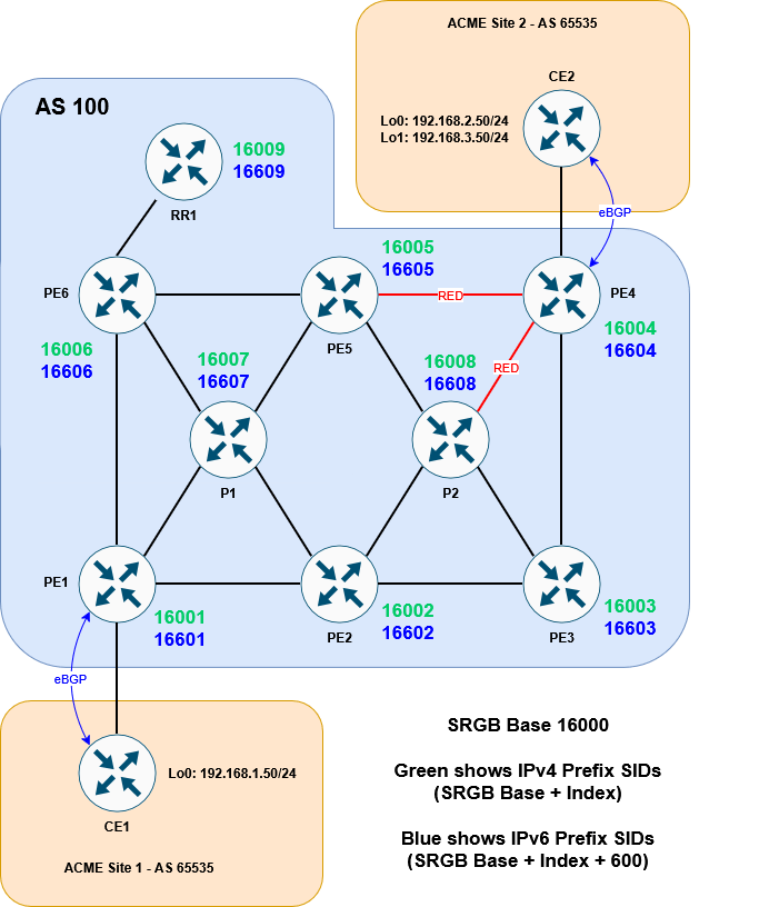
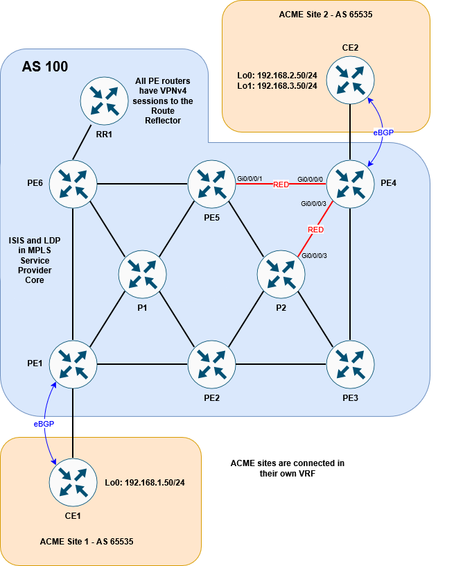
Here is the topology we will be working with:

It’s a basic MPLS network, running ISIS + LDP in the core. VPNv4 routes are exchanged via the router reflector. CE1 and CE2 are customer devices connected via BGP to the Service Provider – placed inside VRF ACME.
I’ve built this lab in EVE-NG. If you have your own setup, you can download the lab and/or config files here to follow along:


The EVE-NG lab consists of:
11 x Cisco XRv 9k 7.9.2s and 2 x Cisco XE 17.03.02s
Login creds are user1/user123
The goal
As mentioned above, our goal here is to connect two SR policies together. The first policy will direct traffic from PE1 to PE5 using an explicit path. The second policy will direct traffic from PE5 to PE4 by dynamically avoiding red colored links.
Here it is in diagram form:

Whilst this is only a lab environment, this kind of traffic engineering could be used in larger environments to do tasks such as steering traffic towards DDoS scrubbers, avoiding maintenance links or crossing administrative boundaries.
If we were using MPLS RSVP to signal the separate paths, all the LSRs would need to reserve and maintain the required state. This would be done using RSVP Path or Resv message (more details here). Segment Routing can accomplish this much more efficiently.
We’ll begin by looking at the base state of the network, then walk through the steps to enable SR, before finally creating the policies.
The setup
Let’s start by checking out the ISIS and LDP config. Here is a sample from PE1:
RP/0/RP0/CPU0:PE1#sh run router isis
Fri Nov  7 20:20:35.436 UTC
router isis ISIS1
 is-type level-2-only
 net 49.0001.0100.0000.0001.00
 mpls ldp sync
 address-family ipv4 unicast
  metric-style wide
  advertise passive-only
  mpls ldp auto-config
 !
 address-family ipv6 unicast
  metric-style wide
  advertise passive-only
  single-topology
 !
 interface Loopback0
  passive
  address-family ipv4 unicast
  !
  address-family ipv6 unicast
  !
 !
 interface GigabitEthernet0/0/0/0
  point-to-point
  address-family ipv4 unicast
  !
  address-family ipv6 unicast
  !
 !
 interface GigabitEthernet0/0/0/2
  point-to-point
  address-family ipv4 unicast
  !
  address-family ipv6 unicast
  !
 !
 interface GigabitEthernet0/0/0/3
  point-to-point
  address-family ipv4 unicast
  !
  address-family ipv6 unicast
  !
 !
!

RP/0/RP0/CPU0:PE1#
PE1 has a VRF called ACME configured with a BGP session to the CE2:
RP/0/RP0/CPU0:PE1#sh run router bgp
Fri Nov  7 20:21:03.711 UTC
router bgp 100
 address-family vpnv4 unicast
 !
 address-family vpnv6 unicast
 !
 neighbor-group RR
  remote-as 100
  update-source Loopback0
  address-family vpnv4 unicast
  !
  address-family vpnv6 unicast
  !
 !
 neighbor 10.1.1.9
  use neighbor-group RR
 !
 vrf ACME
  address-family ipv4 unicast
  !
  address-family ipv6 unicast
  !
  neighbor 172.16.1.2
   remote-as 65535
   address-family ipv4 unicast
    route-policy ALLOW-ALL in
    route-policy ALLOW-ALL out
    as-override
   !
  !
  neighbor 2001:ce1::2
   remote-as 65535
   address-family ipv6 unicast
    route-policy ALLOW-ALL in
    route-policy ALLOW-ALL out
    as-override
   !
  !
 !
!

RP/0/RP0/CPU0:PE1# sh bgp vrf ACME neighbors 172.16.1.2 routes
Fri Nov  7 20:21:23.859 UTC
BGP VRF ACME, state: Active
BGP Route Distinguisher: 100:1
VRF ID: 0x60000001
BGP router identifier 10.1.1.1, local AS number 100
Non-stop routing is enabled
BGP table state: Active
Table ID: 0xe0000001   RD version: 10
BGP main routing table version 10
BGP NSR Initial initsync version 4 (Reached)
BGP NSR/ISSU Sync-Group versions 0/0

Status codes: s suppressed, d damped, h history, * valid, > best
              i - internal, r RIB-failure, S stale, N Nexthop-discard
Origin codes: i - IGP, e - EGP, ? - incomplete
   Network            Next Hop            Metric LocPrf Weight Path
Route Distinguisher: 100:1 (default for vrf ACME)
Route Distinguisher Version: 10
*> 192.168.1.0/24     172.16.1.2               0             0 65535 i

Processed 1 prefixes, 1 paths
RP/0/RP0/CPU0:PE1#
The same type of session is configured between PE4 and CE2. This is all fairly stock standard for a Service Provider environment. We can demonstrate the basic MPLS network by running a traceroute from CE1 to CE2 (sourcing with CE1 Loopback 0 to emulate a LAN).
(NB. For the sake of this lab, the label ranges for each if the LSRs have been set to 24×00 – 24×99, where x is the identifier for that router – PE1 has identifier 1 etc.)
CE1#traceroute 192.168.2.50 source lo0
Type escape sequence to abort.
Tracing the route to 192.168.2.50
VRF info: (vrf in name/id, vrf out name/id)
  1 172.16.1.1 3 msec 2 msec 2 msec
  2 10.10.16.6 [MPLS: Labels 24607/24407 Exp 0] 4 msec
    10.10.17.7 [MPLS: Labels 24707/24407 Exp 0] 4 msec 4 msec
  3 10.10.57.5 [MPLS: Labels 24507/24407 Exp 0] 3 msec
    10.10.56.5 [MPLS: Labels 24507/24407 Exp 0] 3 msec 3 msec
  4 10.10.45.4 [MPLS: Label 24407 Exp 0] 4 msec
    10.10.48.4 [MPLS: Label 24407 Exp 0] 3 msec
    10.10.45.4 [MPLS: Label 24407 Exp 0] 3 msec
  5 172.16.2.2 3 msec *  5 msec
CE1#
You can see the traffic is taking a standard ECMP path through the network. Now let’s look at getting SR working
Setting up SR
Enable Segment Routing
The first step is to enable SR and assign prefix SIDs (don’t forget to enable mpls traffic engineering router-id as well!).
We’ll set the SRGB base to be 16000 across all devices and give sequential IPv4 indexes to each router (PE1 will be SID index 1 etc.). The IPv6 indexes will be the same but +600.
RP/0/RP0/CPU0:PE1#conf t
Fri Nov  7 20:23:21.489 UTC
RP/0/RP0/CPU0:PE1(config)#router isis ISIS1
RP/0/RP0/CPU0:PE1(config-isis)# address-family ipv4 unicast
RP/0/RP0/CPU0:PE1(config-isis-af)#  segment-routing mpls sr-prefer
RP/0/RP0/CPU0:PE1(config-isis-af)#  router-id lo0
RP/0/RP0/CPU0:PE1(config-isis-af)# !
RP/0/RP0/CPU0:PE1(config-isis-af)# address-family ipv6 unicast
RP/0/RP0/CPU0:PE1(config-isis-af)#  segment-routing mpls sr-prefer
RP/0/RP0/CPU0:PE1(config-isis-af)#  router-id lo0
RP/0/RP0/CPU0:PE1(config-isis-af)# !
RP/0/RP0/CPU0:PE1(config-isis-af)# interface Loopback0
RP/0/RP0/CPU0:PE1(config-isis-if)#  address-family ipv4 unicast
RP/0/RP0/CPU0:PE1(config-isis-if-af)#   prefix-sid index 1
RP/0/RP0/CPU0:PE1(config-isis-if-af)#  !
RP/0/RP0/CPU0:PE1(config-isis-if-af)#  address-family ipv6 unicast
RP/0/RP0/CPU0:PE1(config-isis-if-af)#   prefix-sid index 601
RP/0/RP0/CPU0:PE1(config-isis-if-af)#  !
RP/0/RP0/CPU0:PE1(config-isis-if-af)# !
RP/0/RP0/CPU0:PE1(config-isis-if-af)#!
RP/0/RP0/CPU0:PE1(config-isis-if-af)#segment-routing
RP/0/RP0/CPU0:PE1(config-sr)# global-block 16000 23999
RP/0/RP0/CPU0:PE1(config-sr)#commit
Fri Nov  7 20:24:01.542 UTC
RP/0/RP0/CPU0:Nov  7 20:24:03.706 UTC: bgp[1094]: %ROUTING-BGP-2-SR_CFG_CHANGED : SRGB range config has been changed. BGP's labels have to be re-programmed as per new range, 'process restart bgp' needed
RP/0/RP0/CPU0:PE1(config-sr)#
RP/0/RP0/CPU0:PE1#
I’ve enabled the router ID using the router-id lo0 command here, which works under ipv4 and ipv6. An alternative is to use mpls traffic-eng router-id lo0. This might already be in place if you are migrating from traditional MPLS-TE, but it’s only applicable to the ipv4 address-family.
Once we repeat this for all the Service Provider routers, we can see that the MPLS forwarding table now prefers Segment Routing:
RP/0/RP0/CPU0:PE1#sh mpls forwarding
Fri Nov  7 20:29:20.862 UTC
Local  Outgoing    Prefix             Outgoing     Next Hop        Bytes
Label  Label       or ID              Interface                    Switched
------ ----------- ------------------ ------------ --------------- ------------
16001  Aggregate   SR Pfx (idx 1)     default                      0
16002  Pop         SR Pfx (idx 2)     Gi0/0/0/3    10.10.12.2      0
16003  16003       SR Pfx (idx 3)     Gi0/0/0/3    10.10.12.2      0
16004  16004       SR Pfx (idx 4)     Gi0/0/0/0    10.10.16.6      0
       16004       SR Pfx (idx 4)     Gi0/0/0/3    10.10.12.2      0
       16004       SR Pfx (idx 4)     Gi0/0/0/2    10.10.17.7      0
16005  16005       SR Pfx (idx 5)     Gi0/0/0/0    10.10.16.6      0
       16005       SR Pfx (idx 5)     Gi0/0/0/3    10.10.12.2      0
       16005       SR Pfx (idx 5)     Gi0/0/0/2    10.10.17.7      0
16006  Pop         SR Pfx (idx 6)     Gi0/0/0/0    10.10.16.6      0
16007  Pop         SR Pfx (idx 7)     Gi0/0/0/2    10.10.17.7      0
16008  16008       SR Pfx (idx 8)     Gi0/0/0/3    10.10.12.2      0
16009  16009       SR Pfx (idx 9)     Gi0/0/0/0    10.10.16.6      0
16601  Aggregate   SR Pfx (idx 601)   default                      0
16602  Pop         SR Pfx (idx 602)   Gi0/0/0/3    fe80::5200:ff:fe05:6   \
                                                                   0
16603  16603       SR Pfx (idx 603)   Gi0/0/0/3    fe80::5200:ff:fe05:6   \
                                                                   0
16604  16604       SR Pfx (idx 604)   Gi0/0/0/0    fe80::5200:ff:fe02:4   \
                                                                   0
       16604       SR Pfx (idx 604)   Gi0/0/0/3    fe80::5200:ff:fe05:6   \
                                                                   0
       16604       SR Pfx (idx 604)   Gi0/0/0/2    fe80::5200:ff:fe04:5   \
                                                                   0
16605  16605       SR Pfx (idx 605)   Gi0/0/0/0    fe80::5200:ff:fe02:4   \
                                                                   0
       16605       SR Pfx (idx 605)   Gi0/0/0/3    fe80::5200:ff:fe05:6   \
                                                                   0
       16605       SR Pfx (idx 605)   Gi0/0/0/2    fe80::5200:ff:fe04:5   \
                                                                   0
16606  Pop         SR Pfx (idx 606)   Gi0/0/0/0    fe80::5200:ff:fe02:4   \
                                                                   0
16607  Pop         SR Pfx (idx 607)   Gi0/0/0/2    fe80::5200:ff:fe04:5   \
                                                                   0
16608  16608       SR Pfx (idx 608)   Gi0/0/0/3    fe80::5200:ff:fe05:6   \
                                                                   0
16609  16609       SR Pfx (idx 609)   Gi0/0/0/0    fe80::5200:ff:fe02:4   \
                                                                   59
24100  24600       10.1.1.9/32        Gi0/0/0/0    10.10.16.6      0
24101  Pop         10.1.1.6/32        Gi0/0/0/0    10.10.16.6      196
24102  24601       10.1.1.5/32        Gi0/0/0/0    10.10.16.6      0
       24204       10.1.1.5/32        Gi0/0/0/3    10.10.12.2      0
       24703       10.1.1.5/32        Gi0/0/0/2    10.10.17.7      0
24103  Pop         10.1.1.7/32        Gi0/0/0/2    10.10.17.7      98
24104  24201       10.1.1.8/32        Gi0/0/0/3    10.10.12.2      0
24105  24206       10.1.1.3/32        Gi0/0/0/3    10.10.12.2      0
24106  Unlabelled  192.168.1.0/24[V]  Gi0/0/0/1    172.16.1.2      0
24107  Unlabelled  2001:ac73:1::/64[V]   \
                                      Gi0/0/0/1    fe80::5200:ff:fe06:0   \
                                                                   0
24108  Pop         10.1.1.2/32        Gi0/0/0/3    10.10.12.2      334
24109  24607       10.1.1.4/32        Gi0/0/0/0    10.10.16.6      0
       24205       10.1.1.4/32        Gi0/0/0/3    10.10.12.2      0
       24707       10.1.1.4/32        Gi0/0/0/2    10.10.17.7      0
24110  Pop         SR Adj (idx 1)     Gi0/0/0/3    10.10.12.2      0
24111  Pop         SR Adj (idx 3)     Gi0/0/0/3    10.10.12.2      0
24112  Pop         SR Adj (idx 1)     Gi0/0/0/0    10.10.16.6      0
24113  Pop         SR Adj (idx 3)     Gi0/0/0/0    10.10.16.6      0
24114  Pop         SR Adj (idx 1)     Gi0/0/0/2    10.10.17.7      0
24115  Pop         SR Adj (idx 3)     Gi0/0/0/2    10.10.17.7      0
24116  Pop         SR Adj (idx 1)     Gi0/0/0/3    fe80::5200:ff:fe05:6   \
                                                                   0
24117  Pop         SR Adj (idx 3)     Gi0/0/0/3    fe80::5200:ff:fe05:6   \
                                                                   0
24118  Pop         SR Adj (idx 1)     Gi0/0/0/0    fe80::5200:ff:fe02:4   \
                                                                   0
24119  Pop         SR Adj (idx 3)     Gi0/0/0/0    fe80::5200:ff:fe02:4   \
                                                                   0
24120  Pop         SR Adj (idx 1)     Gi0/0/0/2    fe80::5200:ff:fe04:5   \
                                                                   0
24121  Pop         SR Adj (idx 3)     Gi0/0/0/2    fe80::5200:ff:fe04:5   \
                                                                   0
RP/0/RP0/CPU0:PE1#
And indeed, if we repeat our traceroute we can see that SR labels are now used:
CE1#traceroute 192.168.2.50 source lo0
Type escape sequence to abort.
Tracing the route to 192.168.2.50
VRF info: (vrf in name/id, vrf out name/id)
  1 172.16.1.1 3 msec 1 msec 2 msec
  2 10.10.16.6 [MPLS: Labels 16004/24407 Exp 0] 5 msec
    10.10.17.7 [MPLS: Labels 16004/24407 Exp 0] 4 msec
    10.10.16.6 [MPLS: Labels 16004/24407 Exp 0] 4 msec
  3 10.10.56.5 [MPLS: Labels 16004/24407 Exp 0] 3 msec 3 msec
    10.10.57.5 [MPLS: Labels 16004/24407 Exp 0] 3 msec
  4 10.10.45.4 [MPLS: Label 24407 Exp 0] 4 msec
    10.10.48.4 [MPLS: Label 24407 Exp 0] 4 msec
    10.10.45.4 [MPLS: Label 24407 Exp 0] 3 msec
  5 172.16.2.2 3 msec *  4 msec
CE1#
ECMP is still in effect, but since the transport label stays as 16004 the whole way, we’d need to look at the IP addresses to determine the exact path.
Populate SRTE Database
From here we need to populate the SRTE database so that any dynamic policies (in our case the one that avoids RED links) can calculate their best path. This is done using the distribute link-state command under ISIS:
RP/0/RP0/CPU0:PE1#conf t
Fri Nov  7 20:30:46.177 UTC
RP/0/RP0/CPU0:PE1(config)#router isis ISIS1
RP/0/RP0/CPU0:PE1(config-isis)#distribute link-state
RP/0/RP0/CPU0:PE1(config-isis)#commit
Fri Nov  7 20:31:05.594 UTC
RP/0/RP0/CPU0:PE1(config-isis)#
RP/0/RP0/CPU0:PE1#
Once this is done across all the devices, we can see the topology by running the following command:
RP/0/RP0/CPU0:PE2#show segment-routing traffic-eng topology
Fri Nov  7 20:32:16.003 UTC

Topology database:
------------------
Node 11
  Router ID: 10.1.1.1

  ISIS-L2 0100.0000.0001
    Hostname: PE1
    TE router ID: 10.1.1.1
    IPv6 router ID: 2001:1ab::1
    ISIS area ID: 49.0001
    SRGBs: 16000 - 24000
    SRLBs: 15000 - 16000

    Prefixes:
      10.1.1.1/32
        Regular SID index: 1
      2001:1ab::1/128
        Regular SID index: 601

    Links:
      Local: 10.10.12.1 Remote: 10.10.12.2
        Remote node: ISIS-L2 0100.0000.0002
          Hostname: PE2
          TE router ID: 10.1.1.2
          IPv6 router ID: 2001:1ab::2
          ISIS area ID: 49.0001
        Metrics: IGP 10
        Bandwidth: Total 125000000 Bps, Reservable 0 Bps
        Adj-SIDs: 24111 (unprotected), 24117 (unprotected)

      Local: 10.10.16.1 Remote: 10.10.16.6
        Remote node: ISIS-L2 0100.0000.0006
          Hostname: PE6
          TE router ID: 10.1.1.6
          IPv6 router ID: 2001:1ab::6
          ISIS area ID: 49.0001
        Metrics: IGP 10
        Bandwidth: Total 125000000 Bps, Reservable 0 Bps
        Adj-SIDs: 24113 (unprotected), 24119 (unprotected)

      Local: 10.10.17.1 Remote: 10.10.17.7
        Remote node: ISIS-L2 0100.0000.0007
          Hostname: P1
          TE router ID: 10.1.1.7
          IPv6 router ID: 2001:1ab::7
          ISIS area ID: 49.0001
        Metrics: IGP 10
        Bandwidth: Total 125000000 Bps, Reservable 0 Bps
        Adj-SIDs: 24115 (unprotected), 24121 (unprotected)

<snip>

Node 19
  Router ID: 10.1.1.9

  ISIS-L2 0100.0000.0009
    Hostname: RR1
    TE router ID: 10.1.1.9
    IPv6 router ID: 2001:1ab::9
    ISIS area ID: 49.0001
    SRGBs: 16000 - 24000
    SRLBs: 15000 - 16000

    Prefixes:
      10.1.1.9/32
        Regular SID index: 9
      2001:1ab::9/128
        Regular SID index: 609

    Links:
      Local: 10.10.69.9 Remote: 10.10.69.6
        Remote node: ISIS-L2 0100.0000.0006
          Hostname: PE6
          TE router ID: 10.1.1.6
          IPv6 router ID: 2001:1ab::6
          ISIS area ID: 49.0001
        Metrics: IGP 10
        Bandwidth: Total 125000000 Bps, Reservable 0 Bps
        Adj-SIDs: 24909 (unprotected), 24911 (unprotected)

RP/0/RP0/CPU0:PE2#
RP/0/RP0/CPU0:PE2#show segment-routing traffic-eng topology | inc "Node|Local|Bind"
Fri Nov  7 20:33:42.222 UTC
Node 11
    Hostname: PE1
      Local: 10.10.12.1 Remote: 10.10.12.2
          Hostname: PE2
      Local: 10.10.16.1 Remote: 10.10.16.6
          Hostname: PE6
      Local: 10.10.17.1 Remote: 10.10.17.7
          Hostname: P1
Node 12
    Hostname: PE2
      Local: 10.10.12.2 Remote: 10.10.12.1
          Hostname: PE1
      Local: 10.10.23.2 Remote: 10.10.23.3
          Hostname: PE3
      Local: 10.10.25.2 Remote: 10.10.25.5
          Hostname: PE5
      Local: 10.10.27.2 Remote: 10.10.27.7
          Hostname: P1
      Local: 10.10.28.2 Remote: 10.10.28.8
          Hostname: P2
Node 13
    Hostname: PE3
      Local: 10.10.23.3 Remote: 10.10.23.2
          Hostname: PE2
      Local: 10.10.34.3 Remote: 10.10.34.4
          Hostname: PE4
      Local: 10.10.38.3 Remote: 10.10.38.8
          Hostname: P2
Node 14
    Hostname: PE5
      Local: 10.10.25.5 Remote: 10.10.25.2
          Hostname: PE2
      Local: 10.10.45.5 Remote: 10.10.45.4
          Hostname: PE4
      Local: 10.10.56.5 Remote: 10.10.56.6
          Hostname: PE6
      Local: 10.10.57.5 Remote: 10.10.57.7
          Hostname: P1
      Local: 10.10.58.5 Remote: 10.10.58.8
          Hostname: P2
Node 15
    Hostname: P1
      Local: 10.10.17.7 Remote: 10.10.17.1
          Hostname: PE1
      Local: 10.10.27.7 Remote: 10.10.27.2
          Hostname: PE2
      Local: 10.10.57.7 Remote: 10.10.57.5
          Hostname: PE5
      Local: 10.10.67.7 Remote: 10.10.67.6
          Hostname: PE6
Node 16
    Hostname: PE4
      Local: 10.10.34.4 Remote: 10.10.34.3
          Hostname: PE3
      Local: 10.10.45.4 Remote: 10.10.45.5
          Hostname: PE5
      Local: 10.10.48.4 Remote: 10.10.48.8
          Hostname: P2
Node 17
    Hostname: PE6
      Local: 10.10.16.6 Remote: 10.10.16.1
          Hostname: PE1
      Local: 10.10.56.6 Remote: 10.10.56.5
          Hostname: PE5
      Local: 10.10.67.6 Remote: 10.10.67.7
          Hostname: P1
      Local: 10.10.69.6 Remote: 10.10.69.9
          Hostname: RR1
Node 18
    Hostname: P2
      Local: 10.10.28.8 Remote: 10.10.28.2
          Hostname: PE2
      Local: 10.10.38.8 Remote: 10.10.38.3
          Hostname: PE3
      Local: 10.10.48.8 Remote: 10.10.48.4
          Hostname: PE4
      Local: 10.10.58.8 Remote: 10.10.58.5
          Hostname: PE5
Node 19
    Hostname: RR1
      Local: 10.10.69.9 Remote: 10.10.69.6
          Hostname: PE6
RP/0/RP0/CPU0:PE2#
All devices within the same domain should show the same output. We are now ready to start setting up the policies.
Configure explicit SR Policy
The first thing to do is set up an explicit segment list that details the path we want the traffic to follow. In our case the path looks like this:

Here is the CLI:
RP/0/RP0/CPU0:PE1#conf t
Fri Nov  7 20:34:54.088 UTC
RP/0/RP0/CPU0:PE1(config)#segment-routing traffic-eng
RP/0/RP0/CPU0:PE1(config-sr-te)#segment-list name LIST-TO-PE5
RP/0/RP0/CPU0:PE1(config-sr-te-sl)#index 10 mpls label 16006
RP/0/RP0/CPU0:PE1(config-sr-te-sl)#index 20 mpls label 16007
RP/0/RP0/CPU0:PE1(config-sr-te-sl)#index 30 mpls label 16005
RP/0/RP0/CPU0:PE1(config-sr-te-sl)#commit
Fri Nov  7 20:34:59.279 UTC
RP/0/RP0/CPU0:PE1(config-sr-te-sl)#
RP/0/RP0/CPU0:PE1#
With this done, we can create an SR policy to reference the explicit path:
RP/0/RP0/CPU0:PE1#conf t
Fri Nov  7 20:36:17.083 UTC
RP/0/RP0/CPU0:PE1(config)#segment-routing traffic-eng
RP/0/RP0/CPU0:PE1(config-sr-te)#policy TO-PE5
RP/0/RP0/CPU0:PE1(config-sr-te-policy)#color 10 end-point ipv4 10.1.1.5
RP/0/RP0/CPU0:PE1(config-sr-te-policy)#candidate-paths preference 100
RP/0/RP0/CPU0:PE1(config-sr-te-policy-path-pref)#explicit segment-list LIST-TO-PE5
RP/0/RP0/CPU0:PE1(config-sr-te-pp-info)#commit
Fri Nov  7 20:37:23.704 UTC
RP/0/RP0/CPU0:PE1(config-sr-te-pp-info)#
RP/0/RP0/CPU0:PE1#
So far so good. Let’s verify that it has come up okay:
RP/0/RP0/CPU0:PE1#show segment-routing traffic-eng policy color 10
Fri Nov  7 20:38:39.694 UTC

SR-TE policy database
---------------------

Color: 10, End-point: 10.1.1.5
  Name: srte_c_10_ep_10.1.1.5
  Status:
    Admin: up  Operational: up for 00:01:14 (since Nov  7 20:37:24.854)
  Candidate-paths:
    Preference: 100 (configuration) (active)
      Name: TO-PE5
      Requested BSID: dynamic
      Constraints:
        Protection Type: protected-preferred
        Maximum SID Depth: 10
      Explicit: segment-list LIST-TO-PE5 (valid)
        Weight: 1, Metric Type: TE
          SID[0]: 16006 [Prefix-SID, 10.1.1.6]
          SID[1]: 16007
          SID[2]: 16005
  Attributes:
    Binding SID: 24123
    Forward Class: Not Configured
    Steering labeled-services disabled: no
    Steering BGP disabled: no
    IPv6 caps enable: yes
    Invalidation drop enabled: no
    Max Install Standby Candidate Paths: 0

RP/0/RP0/CPU0:PE1#
We can see from the policy that it is up, but how do we steer traffic into it?
This is done by attaching a color community to the BGP router that matches the color of the policy. In our case, we’ll tag 192.168.2.0/24 inbound from CE2 with color 10

RP/0/RP0/CPU0:PE4#conf t
Fri Nov  7 20:41:21.957 UTC
RP/0/RP0/CPU0:PE4(config)#extcommunity-set opaque COLOR-10
RP/0/RP0/CPU0:PE4(config-ext)#10
RP/0/RP0/CPU0:PE4(config-ext)#end-set
RP/0/RP0/CPU0:PE4(config)#route-policy FROM-CE2
RP/0/RP0/CPU0:PE4(config-rpl)#if destination in (192.168.2.0/24) then
RP/0/RP0/CPU0:PE4(config-rpl-if)#set extcommunity color COLOR-10
RP/0/RP0/CPU0:PE4(config-rpl-if)#endif
RP/0/RP0/CPU0:PE4(config-rpl)#pass
RP/0/RP0/CPU0:PE4(config-rpl)#end-policy
RP/0/RP0/CPU0:PE4(config)#router bgp 100
RP/0/RP0/CPU0:PE4(config-bgp)#vrf ACME
RP/0/RP0/CPU0:PE4(config-bgp-vrf)#neighbor 172.16.2.2
RP/0/RP0/CPU0:PE4(config-bgp-vrf-nbr)#address-family ipv4 unicast
RP/0/RP0/CPU0:PE4(config-bgp-vrf-nbr-af)#route-policy FROM-CE2 in
RP/0/RP0/CPU0:PE4(config-bgp-vrf-nbr-af)#
Before we commit, here is what the prefix currently looks like in the BGP table:
RP/0/RP0/CPU0:PE4(config-bgp-vrf-nbr-af)#do show bgp vrf ACME 192.168.2.0
Fri Nov  7 20:41:50.516 UTC
BGP routing table entry for 192.168.2.0/24, Route Distinguisher: 100:1
Versions:
  Process           bRIB/RIB  SendTblVer
  Speaker                  14           14
    Local Label: 24407
Last Modified: Nov  7 20:41:20.501 for 00:00:30
Paths: (1 available, best #1)
  Advertised to PE peers (in unique update groups):
    10.1.1.9
  Path #1: Received by speaker 0
  Advertised to PE peers (in unique update groups):
    10.1.1.9
  65535
    172.16.2.2 from 172.16.2.2 (192.168.3.50)
      Origin IGP, metric 0, localpref 100, valid, external, best, group-best, import-candidate
      Received Path ID 0, Local Path ID 1, version 14
      Extended community: RT:100:1
      Origin-AS validity: (disabled)
RP/0/RP0/CPU0:PE4(config-bgp-vrf-nbr-af)#
The additon of the color can be seen once we commit:
RP/0/RP0/CPU0:PE4(config-bgp-vrf-nbr-af)#commit
Fri Nov  7 20:42:10.086 UTC
RP/0/RP0/CPU0:PE4(config-bgp-vrf-nbr-af)#
RP/0/RP0/CPU0:PE4#show bgp vrf ACME 192.168.2.0
Fri Nov  7 20:42:19.644 UTC
BGP routing table entry for 192.168.2.0/24, Route Distinguisher: 100:1
Versions:
  Process           bRIB/RIB  SendTblVer
  Speaker                  16           16
    Local Label: 24407
Last Modified: Nov  7 20:42:12.501 for 00:00:07
Paths: (1 available, best #1)
  Advertised to PE peers (in unique update groups):
    10.1.1.9
  Path #1: Received by speaker 0
  Advertised to PE peers (in unique update groups):
    10.1.1.9
  65535
    172.16.2.2 from 172.16.2.2 (192.168.3.50)
      Origin IGP, metric 0, localpref 100, valid, external, best, group-best, import-candidate
      Received Path ID 0, Local Path ID 1, version 16
      Extended community: Color:10 RT:100:1
      Origin-AS validity: (disabled)
RP/0/RP0/CPU0:PE4#
Note that this has only been applied to 192.168.2.0/24, not 192.168.3.0/24:
RP/0/RP0/CPU0:PE4#show bgp vrf ACME 192.168.3.0
Fri Nov  7 20:42:53.104 UTC
BGP routing table entry for 192.168.3.0/24, Route Distinguisher: 100:1
Versions:
  Process           bRIB/RIB  SendTblVer
  Speaker                  15           15
    Local Label: 24409
Last Modified: Nov  7 20:41:20.501 for 00:01:32
Paths: (1 available, best #1)
  Advertised to PE peers (in unique update groups):
    10.1.1.9
  Path #1: Received by speaker 0
  Advertised to PE peers (in unique update groups):
    10.1.1.9
  65535
    172.16.2.2 from 172.16.2.2 (192.168.3.50)
      Origin IGP, metric 0, localpref 100, valid, external, best, group-best, import-candidate
      Received Path ID 0, Local Path ID 1, version 15
      Extended community: RT:100:1
      Origin-AS validity: (disabled)
RP/0/RP0/CPU0:PE4#
PE1 sees the color as well:
RP/0/RP0/CPU0:PE1#sh bgp vrf ACME 192.168.2.0/24
Fri Nov  7 20:43:32.410 UTC
BGP routing table entry for 192.168.2.0/24, Route Distinguisher: 100:1
Versions:
  Process           bRIB/RIB  SendTblVer
  Speaker                  18           18
Last Modified: Nov  7 20:42:12.284 for 00:01:20
Paths: (1 available, best #1)
  Advertised to CE peers (in unique update groups):
    172.16.1.2
  Path #1: Received by speaker 0
  Advertised to CE peers (in unique update groups):
    172.16.1.2
  65535
    10.1.1.4 (metric 30) from 10.1.1.9 (10.1.1.4)
      Received Label 24407
      Origin IGP, metric 0, localpref 100, valid, internal, best, group-best, import-candidate, imported
      Received Path ID 0, Local Path ID 1, version 18
      Extended community: Color:10 RT:100:1
      Originator: 10.1.1.4, Cluster list: 10.1.1.9
      Source AFI: VPNv4 Unicast, Source VRF: ACME, Source Route Distinguisher: 100:1
RP/0/RP0/CPU0:PE1#
The idea here is for traffic to 192.168.20/24 to be directed into our color 10 tunnel. If this is working, we should see the CEF table on the ACME VRF recurving to the Binding SID for our SR Policy (if you look above, the Binding SID is 24123)…
RP/0/RP0/CPU0:PE1#show cef vrf ACME 192.168.2.0
Fri Nov  7 20:44:08.498 UTC
192.168.2.0/24, version 17, internal 0x5000001 0x30 (ptr 0xe9d5288) [1], 0x600 (0xd6f8dd8), 0xa08 (0xf549510)
 Updated Nov  7 20:42:11.812
 Prefix Len 24, traffic index 0, precedence n/a, priority 3
  gateway array (0xd5524d8) reference count 2, flags 0x38, source rib (7), 0 backups
                [3 type 1 flags 0x8441 (0xf583358) ext 0x0 (0x0)]
  LW-LDI[type=1, refc=1, ptr=0xd6f8dd8, sh-ldi=0xf583358]
  gateway array update type-time 1 Nov  7 20:41:19.728
 LDI Update time Nov  7 20:41:19.729
 LW-LDI-TS Nov  7 20:41:19.729
   via 10.1.1.4/32, 5 dependencies, recursive [flags 0x6000]
    path-idx 0 NHID 0x0 [0xd8bf740 0x0]
    recursion-via-/32
    next hop VRF - 'default', table - 0xe0000000
    next hop 10.1.1.4/32 via 16004/0/21
     next hop 10.10.16.6/32 Gi0/0/0/0    labels imposed {16004 24407}
     next hop 10.10.12.2/32 Gi0/0/0/3    labels imposed {16004 24407}
     next hop 10.10.17.7/32 Gi0/0/0/2    labels imposed {16004 24407}

    Load distribution: 0 (refcount 3)

    Hash  OK  Interface                 Address
    0     Y   recursive                 16004/0
RP/0/RP0/CPU0:PE1#
But here, it looks like it is still just imposing 16004 (the SID for R4) and then 24407 (the VPNv4 label for 192.168.2.0/24). It’s then ECMP’ing it out of Gi0/0/0/0, Gi0/0/0/3 and Gi0/0/0/2.
So what gives? Why is it not using our SR Policy?
Well, we have to remember that the allocation of a prefix to a policy is based on the combination of the end-point and the color. Looking at the BGP route, the color is correct, but the end point (or next-hop in BGP talk) is still 10.1.1.4 – PE4. Our policy is defined as having an end-point of 10.1.1.5!
So let’s fix that:
RP/0/RP0/CPU0:PE1#conf t
Fri Nov  7 20:45:04.898 UTC
RP/0/RP0/CPU0:PE1(config)#segment-routing traffic-eng
RP/0/RP0/CPU0:PE1(config-sr-te)#policy TO-PE5
RP/0/RP0/CPU0:PE1(config-sr-te-policy)#color 10 end-point ipv4 10.1.1.4
RP/0/RP0/CPU0:PE1(config-sr-te-policy)#commit
Fri Nov  7 20:45:31.664 UTC
RP/0/RP0/CPU0:PE1(config-sr-te-policy)#
RP/0/RP0/CPU0:PE1#
Now we see that it is correctly steering down the SR policy:
RP/0/RP0/CPU0:PE1#sh segment-routing traffic-eng policy color 10 | inc "Operation|Bind"
Fri Nov  7 20:46:53.444 UTC
    Admin: up  Operational: up for 00:01:21 (since Nov  7 20:45:31.897)
    Binding SID: 24125
RP/0/RP0/CPU0:PE1#show cef vrf ACME 192.168.2.0
Fri Nov  7 20:47:05.492 UTC
192.168.2.0/24, version 21, internal 0x5000001 0x30 (ptr 0xe9d5288) [1], 0x600 (0xd6f8dd8), 0xa08 (0xf54a068)
 Updated Nov  7 20:45:31.910
 Prefix Len 24, traffic index 0, precedence n/a, priority 3
  gateway array (0xd553440) reference count 1, flags 0x38, source rib (7), 0 backups
                [2 type 1 flags 0x8441 (0xf584328) ext 0x0 (0x0)]
  LW-LDI[type=1, refc=1, ptr=0xd6f8dd8, sh-ldi=0xf584328]
  gateway array update type-time 1 Nov  7 20:45:31.910
 LDI Update time Nov  7 20:45:31.910
 LW-LDI-TS Nov  7 20:45:31.910
   via local-label 24125, 3 dependencies, recursive [flags 0x6000]
    path-idx 0 NHID 0x0 [0xd8bb388 0x0]
    recursion-via-label
    next hop VRF - 'default', table - 0xe0000000
    next hop via 24125/0/21
     next hop srte_c_10_ep labels imposed {ImplNull 24407}

    Load distribution: 0 (refcount 2)

    Hash  OK  Interface                 Address
    0     Y   recursive                 24125/0
RP/0/RP0/CPU0:PE1#
The Binding SID has changed to 24125 since we refreshed the endpoint, but CEF is looking good.
However, whilst this is steering the traffic into the policy, it still won’t get us all the way. If trace from CE1 we can see that we just get stars:
CE1#traceroute 192.168.2.50 source lo0
Type escape sequence to abort.
Tracing the route to 192.168.2.50
VRF info: (vrf in name/id, vrf out name/id)
1 172.16.1.1 47 msec 1 msec 2 msec
2 * * *
3 * * *
4 * * *
5 * * *
6 * * *
7 *
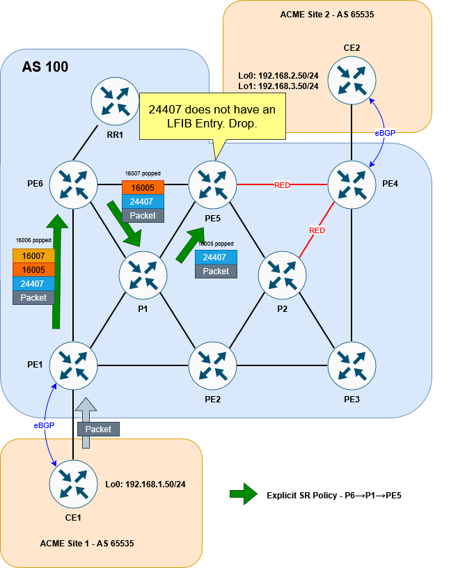
CE1#The reason for this is fairly simple. This is the stack we are putting on the packet to CE2:
16006 (PE6 Prefix SID)
16007 (P1 Prefix SID)
16005 (PE5 Prefix SID)
24407 (VPN label)
As each segment is completed, the top label is popped. We can very quickly see that when the packet reaches PE5 the VPN label is exposed. But PE5 has no idea what to do with it! This VPN label was allocated by PE4 not PE5!
For our solution, this is okay at this point in the setup. Remember we will be wanting to push this traffic into a second policy that avoids all RED links and does end up at PE4.
For now, and just for the sake of getting our traceroute working, let’s add the PE4 label to the bottom of our explicit stack, so that PE5 can forward traffic on to PE4. We’ll remove this later:
RP/0/RP0/CPU0:PE1#conf t
Fri Nov  7 20:49:52.903 UTC
RP/0/RP0/CPU0:PE1(config)#segment-routing
RP/0/RP0/CPU0:PE1(config-sr)#traffic-eng
RP/0/RP0/CPU0:PE1(config-sr-te)#segment-list LIST-TO-PE5
RP/0/RP0/CPU0:PE1(config-sr-te-sl)#index 40 mpls label 16004
RP/0/RP0/CPU0:PE1(config-sr-te-sl)#commit
Fri Nov  7 20:50:03.914 UTC
RP/0/RP0/CPU0:PE1(config-sr-te-sl)#
RP/0/RP0/CPU0:PE1#
Now a traceroute works correctly:
CE1#traceroute 192.168.2.50 source lo0
Type escape sequence to abort.
Tracing the route to 192.168.2.50
VRF info: (vrf in name/id, vrf out name/id)
  1 172.16.1.1 3 msec 2 msec 2 msec
  2 10.10.16.6 [MPLS: Labels 16007/16005/16004/24407 Exp 0] 5 msec 3 msec 4 msec
  3 10.10.67.7 [MPLS: Labels 16005/16004/24407 Exp 0] 4 msec 3 msec 3 msec
  4 10.10.57.5 [MPLS: Labels 16004/24407 Exp 0] 7 msec 3 msec 3 msec
  5 10.10.45.4 [MPLS: Label 24407 Exp 0] 3 msec 3 msec 3 msec
  6 172.16.2.2 3 msec *  5 msec
CE1#
For the explicit path to PE5 to work, we need to make sure that a label that PE5 is going to understand is exposed. To get that, we need to configure the second policy from PE4…
Configure dynamic SR Policy
This policy isn’t going to be explicitly defined. Rather, we’re going to define the conditions of the policy (namely to avoid red links) and let the head end router figure it out. The first step in creating a dynamic policy that avoids red links is to, well, configure some RED links!
As a reminder, these are the links we want to color red:
Before going any further, let’s get some clarity on the term color and the different ways it is used within the context of this lab.
Color
This scenario uses the term color to refer to multiple different things and it can get confusing if you don’t know what you’re looking at. The two ways we’re concerned with color are as follows:
Policy Coloring
The first, is the color that we have already seen when defining an SR policy. This is an identifier for the policy. If a prefix is tagged with that color (in the case of BGP, it will be an attribute) and its next-hop matches the policy endpoint, traffic to that prefix will be steered into the policy. This is exactly how we’ve steered traffic into our explicit tunnel at PE1.
Link Coloring
The second way in which color is used is with regards to link coloring. Coloring a connection between two devices works by using something called link affinities (also called Admin group from the MPLS TE RSVP days). When we entered the distribute-link state command above, ISIS started to advertise Segment Routing details in its TLVs. This includes details about the links themselves – like metric, delay and link affinities. The link affinity is basically a string made up of ones and zeros that we can set and use how we wish. In this case, we’re using the affinity to “color” a link. I put the word “color” in air quotes, because from a CLI perspective, the word color isn’t actually referenced. We engineers use the term color because it’s easy to visualise a link that way.
This section looks at the latter of the two color definitions. Within the CLI the link-affinity is referenced as an integer number. For our scenario, let’s make 7 represent RED. Here’s how it would look:
RP/0/RP0/CPU0:PE4#conf t
Fri Nov  7 20:52:55.870 UTC
RP/0/RP0/CPU0:PE4(config)#segment-routing traffic-eng
RP/0/RP0/CPU0:PE4(config-sr-te)#affinity-map name RED bit-position 7
RP/0/RP0/CPU0:PE4(config-sr-te)#interface GigabitEthernet0/0/0/0
RP/0/RP0/CPU0:PE4(config-sr-if)#affinity
RP/0/RP0/CPU0:PE4(config-sr-if-affinity)#name RED
RP/0/RP0/CPU0:PE4(config-sr-if-affinity)#interface GigabitEthernet0/0/0/3
RP/0/RP0/CPU0:PE4(config-sr-if)#affinity
RP/0/RP0/CPU0:PE4(config-sr-if-affinity)#name RED
RP/0/RP0/CPU0:PE4(config-sr-if-affinity)#commit
Fri Nov  7 20:53:04.345 UTC
RP/0/RP0/CPU0:PE4(config-sr-if-affinity)#
RP/0/RP0/CPU0:PE4#
NB. As a side note, if you are configuring colors for different Flex-Algos, that config would go under the IGP (ISIS) and not under segment-routing. I won’t detail this here, but the principle of link coloring, with or without Flex-Algo, is the same.
Now that we’ve colored the link we can verify it:
RP/0/RP0/CPU0:PE4#show segment-routing traffic-eng topology | inc "Host|Link|Admin"
Fri Nov  7 20:54:14.682 UTC
<snip>
    Hostname: PE4
    Links:
          Hostname: PE3
          Hostname: PE5
        Admin groups: 0x00000080 0x00000000 0x00000000 0x00000000
          Hostname: P2
        Admin groups: 0x00000080 0x00000000 0x00000000 0x00000000
<snip>
RP/0/RP0/CPU0:PE4#
The output is a little messy, so I’ve piped the command and omitted the full result, but you can clearly see that the affinity bits (Admin groups) have been set for PE4’s links to PE5 and P2.
The next step would be to configure the policy on PE5 to avoid RED links. This looks similar to the explicit policy we used before but it instead uses the (surprise, surprise) dynamic keyword. We’ll give the policy a the color number of 20 (in the SR policy sense, not the link color sense), just to differentiate it from the PE1 – although colors will be locally significant:
RP/0/RP0/CPU0:PE5#conf t
Fri Nov  7 20:57:40.548 UTC
RP/0/RP0/CPU0:PE5(config)#segment-routing traffic-eng
RP/0/RP0/CPU0:PE5(config-sr-te)#policy AVOID-RED
RP/0/RP0/CPU0:PE5(config-sr-te-policy)#color 20 end-point ipv4 10.1.1.4
RP/0/RP0/CPU0:PE5(config-sr-te-policy)#candidate-paths preference 100
RP/0/RP0/CPU0:PE5(config-sr-te-policy-path-pref)#dynamic
RP/0/RP0/CPU0:PE5(config-sr-te-pp-info)#exit
RP/0/RP0/CPU0:PE5(config-sr-te-policy-path-pref)#constraints
RP/0/RP0/CPU0:PE5(config-sr-te-path-pref-const)#affinity
RP/0/RP0/CPU0:PE5(config-sr-te-path-pref-const-aff)#exclude-any name RED
RP/0/RP0/CPU0:PE5(config-sr-te-path-pref-const-aff)#commit
Fri Nov  7 20:57:45.688 UTC
RP/0/RP0/CPU0:PE5(config-sr-te-path-pref-const-aff)#
RP/0/RP0/CPU0:PE5#
Great. Now if we check the policy, we can see that it is up:
RP/0/RP0/CPU0:PE5#sh segment-routing traffic-eng policy color 20
Fri Nov  7 21:15:12.580 UTC

SR-TE policy database
---------------------

Color: 20, End-point: 10.1.1.4
  Name: srte_c_20_ep_10.1.1.4
  Status:
    Admin: up  Operational: up for 00:06:00 (since Nov  7 21:09:12.560)
  Candidate-paths:
    Preference: 100 (configuration) (active)
      Name: AVOID-RED
      Requested BSID: dynamic
      Constraints:
        Protection Type: protected-preferred
        Affinity:
          exclude-any:
          RED
        Maximum SID Depth: 10
      Dynamic (valid)
        Metric Type: TE,   Path Accumulated Metric: 10
          SID[0]: 16004 [Prefix-SID, 10.1.1.4]
  Attributes:
    Binding SID: 24529
    Forward Class: Not Configured
    Steering labeled-services disabled: no
    Steering BGP disabled: no
    IPv6 caps enable: yes
    Invalidation drop enabled: no
    Max Install Standby Candidate Paths: 0

RP/0/RP0/CPU0:PE5#
This might look to be working, but if you look at the SID list, it only appears to be adding 16004 onto the packet. This means it will simply send the traffic straight to PE4 without avoiding the RED links. To prove this, we can look at the LFIB forwarding behaviour for 16004. It just sends it out of the Gi0/0/0/1 interface (direct to PE4!)
RP/0/RP0/CPU0:PE5#sh mpls forwarding labels 16004
Fri Nov  7 21:15:41.648 UTC
Local  Outgoing    Prefix             Outgoing     Next Hop        Bytes
Label  Label       or ID              Interface                    Switched
------ ----------- ------------------ ------------ --------------- ------------
16004  Pop         SR Pfx (idx 4)     Gi0/0/0/1    10.10.45.4      10229
RP/0/RP0/CPU0:PE5#
The reason for this is simple: The end that the link is colored on matters.
We’ve colored Gi0/0/0/0 and Gi0/0/0/3 on PE4. But nothing else.
Gi0/0/0/1 on PE5 isn’t colored RED. This might seem like a limitation, having to color both ends, but it allows traffic in different directions to take different paths, which could be handy depending on the circumstance. To help visualise this, it might be easier to think of the color as being applied to the outbound interface rather than the link as a whole. To put this in diagram form, this is what we’ve done:

So in our case, traffic from PE5 to PE4 will not be considered to be crossing a red link (but traffic from PE4 to PE5 would). We don’t need any multi-directional differences in our lab, so to make this consistent, let’s color the interfaces on PE5 and P2 facing PE4.
RP/0/RP0/CPU0:PE5#conf t
Fri Nov  7 21:16:19.448 UTC
RP/0/RP0/CPU0:PE5(config)#segment-routing traffic-eng
RP/0/RP0/CPU0:PE5(config-sr-te)#interface gigabitEthernet 0/0/0/1
RP/0/RP0/CPU0:PE5(config-sr-if)#affinity name RED
RP/0/RP0/CPU0:PE5(config-sr-if)#commit
Fri Nov  7 21:16:23.781 UTC
RP/0/RP0/CPU0:PE5(config-sr-if)#
RP/0/RP0/CPU0:PE5#
RP/0/RP0/CPU0:P2#conf t
Fri Nov 7 21:16:56.984 UTC
RP/0/RP0/CPU0:P2(config)#segment-routing traffic-eng
RP/0/RP0/CPU0:P2(config-sr-te)#interface gigabitEthernet 0/0/0/3
RP/0/RP0/CPU0:P2(config-sr-if)#affinity name RED
RP/0/RP0/CPU0:P2(config-sr-if)#commit
Fri Nov 7 21:17:02.505 UTC
RP/0/RP0/CPU0:P2(config-sr-if)#
RP/0/RP0/CPU0:P2#With this corrected, here is what our policy on PE5 looks like:
RP/0/RP0/CPU0:PE5#show segment-routing traffic-eng policy color 20
Fri Nov  7 21:17:26.918 UTC

SR-TE policy database
---------------------

Color: 20, End-point: 10.1.1.4
  Name: srte_c_20_ep_10.1.1.4
  Status:
    Admin: up  Operational: up for 00:08:14 (since Nov  7 21:09:12.560)
  Candidate-paths:
    Preference: 100 (configuration) (active)
      Name: AVOID-RED
      Requested BSID: dynamic
      Constraints:
        Protection Type: protected-preferred
        Affinity:
          exclude-any:
          RED
        Maximum SID Depth: 10
      Dynamic (valid)
        Metric Type: TE,   Path Accumulated Metric: 30
          SID[0]: 16008 [Prefix-SID, 10.1.1.8]
          SID[1]: 16003 [Prefix-SID, 10.1.1.3]
          SID[2]: 16004 [Prefix-SID, 10.1.1.4]
  Attributes:
    Binding SID: 24529
    Forward Class: Not Configured
    Steering labeled-services disabled: no
    Steering BGP disabled: no
    IPv6 caps enable: yes
    Invalidation drop enabled: no
    Max Install Standby Candidate Paths: 0

RP/0/RP0/CPU0:PE5#
This is looking much better! The policy is going via PE3 (10.1.1.3), through P2 (10.1.1.8). It is using the Node SID of P2 first, then the node SID of PE3.
Stitching two policies together
Now that we’ve got both policies working, we need to stitch them together at PE5.
We’ve now got both of our policies working:
- The first policy will use an explicit path from PE1 to PE5
- The second policy will use a dynamic path from PE5 to PE4, avoiding red links.
We steered traffic into the first policy by tagging 192.168.2.0/24 with a color attribute 10, so that it matches the color (and endpoint) on PE1’s explicit policy.
But how do we steer traffic into our second policy. Well to understand this, we need to consider different ways that traffic is directed into SR policies:
Directing traffic into an SR Policy
An SR policy is all well and good, but it doesn’t mean much if you can’t actually steer traffic into it. We’ve already seen one way – namely by tagging a BGP route with the right color attribute. But there are other ways to accomplish this.
If the incoming packet is unlabelled you could use a static route, or some form of policy based routing – pseudowires can be configured to prefer a given SR policy etc.
But what we’re interested in here is how incoming labelled traffic enters an SR policy. Afterall, traffic coming from PE1 to PE5 on the explicit path will arrive with labels.
The way to steering labelled traffic into a SR policy is to use what is called the Binding SID of a given policy. The Binding SID is a locally significant label that instructs the router to steer any arriving traffic with that label into the SR policy. The incoming packet with the Binding SID on top, will have the Binding SID removed and then the labels associated with that policy imposed on to it.
We’ve already seen a form of this earlier when looking at the CEF entry for our first policy. The CEF entry showed the local Binding SID as being imposted. This will in turn apply the explicit segment list we specified.
So with this in mind, we need to make sure that traffic arriving at PE5 has the Binding SID for the SR policy that avoids red links. Re-checking the policy on PE5 shows that it has a Binding SID of 24529:
RP/0/RP0/CPU0:PE5#show segment-routing traffic-eng policy color 20 | inc Binding
Fri Nov  7 21:18:31.185 UTC
    Binding SID: 24529
RP/0/RP0/CPU0:PE5#
The Binding SID is automatically generated and comes from a random pool – typically the same pool that LDP labels are pulled from. If PE5 were to reload, this number could change, meaning we’d have to change our policy on PE1. To avoid this, we can statically set the Binding SID as follows:
RP/0/RP0/CPU0:PE5#conf t
Fri Nov  7 21:19:13.130 UTC
RP/0/RP0/CPU0:PE5(config)#segment-routing
RP/0/RP0/CPU0:PE5(config-sr)#traffic-eng
RP/0/RP0/CPU0:PE5(config-sr-te)#policy AVOID-RED
RP/0/RP0/CPU0:PE5(config-sr-te-policy)#binding-sid mpls 24500
RP/0/RP0/CPU0:PE5(config-sr-te-policy)#commit
Fri Nov  7 21:19:19.346 UTC
RP/0/RP0/CPU0:PE5(config-sr-te-policy)#RP/0/RP0/CPU0:Nov  7 21:19:29.482 UTC: xtc_agent[1292]: %OS-XTC-3-SR_POLICY_BSID_UNAVAIL : SR policy 'srte_c_20_ep_10.1.1.4' (color 20, end-point 10.1.1.4) binding-sid 24500 could not be allocated (BSID could not be allocated (check conflicts))

RP/0/RP0/CPU0:PE5(config-sr-te-policy)#
RP/0/RP0/CPU0:PE5#show segment-routing traffic-eng policy color 20
Fri Nov  7 21:19:53.463 UTC

SR-TE policy database
---------------------

Color: 20, End-point: 10.1.1.4
  Name: srte_c_20_ep_10.1.1.4
  Status:
    Admin: up  Operational: down for 00:00:24 (since Nov  7 21:19:29.483)
  Candidate-paths:
    Preference: 100 (configuration) (inactive)
      Name: AVOID-RED
      Last error: BSID could not be allocated (check conflicts): 24500
      Requested BSID: 24500
      Constraints:
        Protection Type: protected-preferred
        Affinity:
          exclude-any:
          RED
        Maximum SID Depth: 10
      Dynamic (inactive)
        Metric Type: TE,   Path Accumulated Metric: 30
  Attributes:
    Forward Class: 0
    Steering labeled-services disabled: no
    Steering BGP disabled: no
    IPv6 caps enable: no
    Invalidation drop enabled: no
    Max Install Standby Candidate Paths: 0

RP/0/RP0/CPU0:PE5#
Whoops. This doesn’t seem to have work. It’s unhappy with 24500, stating that there is a conflict. If we check our MPLS configuration we can see why:
RP/0/RP0/CPU0:PE5#sh run mpls
Fri Nov  7 21:20:26.725 UTC
mpls ldp
!
mpls label range table 0 24500 24599

RP/0/RP0/CPU0:PE5#sh mpls label range
Fri Nov  7 21:20:42.978 UTC
Range for dynamic labels: Min/Max: 24500/24599
RP/0/RP0/CPU0:PE5#
Our dynamic label range has been set to 24500 24599. This is from when we had LDP configured. We can’t set an explicit Binding SID from within a dynamic range. The Explicit binding SID should come from the SRLB which defaults to 15,000 – 15,999.
RP/0/RP0/CPU0:PE5#sh isis database verbose PE5.00-00 | inc Base
Fri Nov  7 21:21:03.444 UTC
    Segment Routing: I:1 V:1, SRGB Base: 16000 Range: 8000
    SR Local Block: Base: 15000 Range: 1000
RP/0/RP0/CPU0:PE5#
We’ll allocate 15005 as the Binding SID:
RP/0/RP0/CPU0:PE5#conf t
Fri Nov  7 21:21:36.904 UTC
RP/0/RP0/CPU0:PE5(config)#segment-routing
RP/0/RP0/CPU0:PE5(config-sr)#traffic-eng
RP/0/RP0/CPU0:PE5(config-sr-te)#policy AVOID-RED
RP/0/RP0/CPU0:PE5(config-sr-te-policy)#binding-sid mpls 15005
RP/0/RP0/CPU0:PE5(config-sr-te-policy)#commit
Fri Nov  7 21:21:41.223 UTC
RP/0/RP0/CPU0:PE5(config-sr-te-policy)#
RP/0/RP0/CPU0:PE5#show segment-routing traffic-eng policy color 20
Fri Nov  7 21:21:46.905 UTC

SR-TE policy database
---------------------

Color: 20, End-point: 10.1.1.4
  Name: srte_c_20_ep_10.1.1.4
  Status:
    Admin: up  Operational: up for 00:00:05 (since Nov  7 21:21:41.348)
  Candidate-paths:
    Preference: 100 (configuration) (active)
      Name: AVOID-RED
      Requested BSID: 15005
      Constraints:
        Protection Type: protected-preferred
        Affinity:
          exclude-any:
          RED
        Maximum SID Depth: 10
      Dynamic (valid)
        Metric Type: TE,   Path Accumulated Metric: 30
          SID[0]: 16008 [Prefix-SID, 10.1.1.8]
          SID[1]: 16003 [Prefix-SID, 10.1.1.3]
          SID[2]: 16004 [Prefix-SID, 10.1.1.4]
  Attributes:
    Binding SID: 15005 (SRLB)
    Forward Class: Not Configured
    Steering labeled-services disabled: no
    Steering BGP disabled: no
    IPv6 caps enable: yes
    Invalidation drop enabled: no
    Max Install Standby Candidate Paths: 0

RP/0/RP0/CPU0:PE5#
Brilliant. Now that we’ve got the Binding SID set, the final step is to change the policy from PE1 to ensure that when traffic arrives at PE5, it has SID 15005 on top.
Remember we previously added 16004 to PE1’s policy. This was just so that PE5 had something it recognised once traffic reached it and our test traceroute could work. We’ll remove that first and replace it with 15005.
RP/0/RP0/CPU0:PE1#conf t
Fri Nov  7 21:22:51.742 UTC
RP/0/RP0/CPU0:PE1(config)#segment-routing
RP/0/RP0/CPU0:PE1(config-sr)#traffic-eng
RP/0/RP0/CPU0:PE1(config-sr-te)#segment-list LIST-TO-PE5
RP/0/RP0/CPU0:PE1(config-sr-te-sl)#no index 40 mpls label 16004
RP/0/RP0/CPU0:PE1(config-sr-te-sl)#index 40 mpls label 15005
RP/0/RP0/CPU0:PE1(config-sr-te-sl)#commit
Fri Nov  7 21:22:57.593 UTC
RP/0/RP0/CPU0:PE1(config-sr-te-sl)#
RP/0/RP0/CPU0:PE1#show segment-routing traffic-eng policy color 10
Fri Nov  7 21:23:02.044 UTC

SR-TE policy database
---------------------

Color: 10, End-point: 10.1.1.4
  Name: srte_c_10_ep_10.1.1.4
  Status:
    Admin: up  Operational: up for 00:37:30 (since Nov  7 20:45:31.897)
  Candidate-paths:
    Preference: 100 (configuration) (active) (reoptimizing)
      Name: TO-PE5
      Requested BSID: dynamic
      Constraints:
        Protection Type: protected-preferred
        Maximum SID Depth: 10
      Explicit: segment-list LIST-TO-PE5 (valid)
        Weight: 1, Metric Type: TE
          SID[0]: 16006 [Prefix-SID, 10.1.1.6]
          SID[1]: 16007
          SID[2]: 16005
          SID[3]: 15005
  Attributes:
    Binding SID: 24125
    Forward Class: Not Configured
    Steering labeled-services disabled: no
    Steering BGP disabled: no
    IPv6 caps enable: yes
    Invalidation drop enabled: no
    Max Install Standby Candidate Paths: 0

RP/0/RP0/CPU0:PE1#
Looking good. Let’s try our traceroute from CE1 to CE2:
CE1#traceroute 192.168.2.50 source lo0
Type escape sequence to abort.
Tracing the route to 192.168.2.50
VRF info: (vrf in name/id, vrf out name/id)
1 172.16.1.1 2 msec 1 msec 2 msec
2 10.10.16.6 [MPLS: Labels 16007/16005/15005/24407 Exp 0] 5 msec 4 msec 4 msec
3 10.10.67.7 [MPLS: Labels 16005/15005/24407 Exp 0] 5 msec 4 msec 3 msec
4 10.10.57.5 [MPLS: Labels 15005/24407 Exp 0] 4 msec 4 msec 4 msec
5 10.10.58.8 [MPLS: Labels 16003/16004/24407 Exp 0] 5 msec 4 msec 4 msec
6 10.10.38.3 [MPLS: Labels 16004/24407 Exp 0] 5 msec 3 msec 3 msec
7 10.10.34.4 [MPLS: Label 24407 Exp 0] 4 msec 4 msec 4 msec
8 172.16.2.2 5 msec * 5 msec
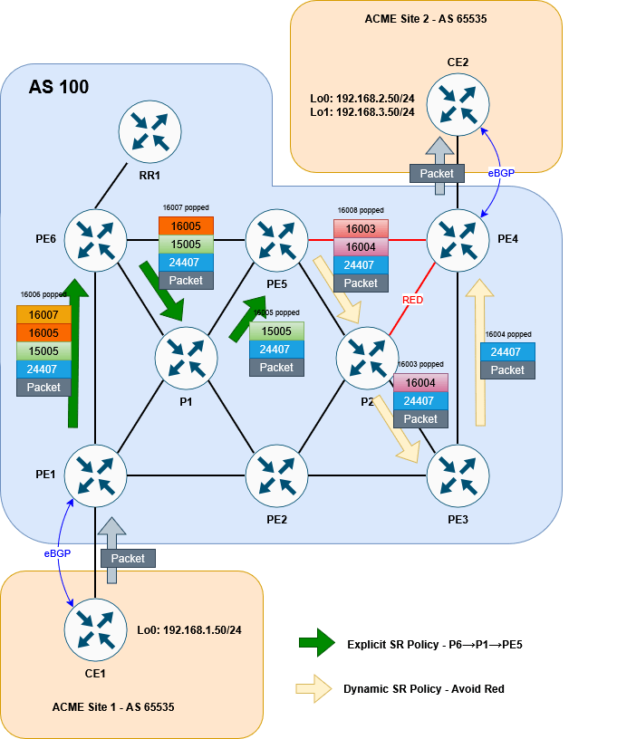
CE1#It works! We can see the traffic following the P6→ P1 → PE5 explicit path, before entering the P4→P5 dynamic path that avoids red using the 15005 label. The 24407 is the VPNv4 advertised from P4 for 192.168.2.0/24.
As proof of concept we can see that tracing to 192.168.3.50 (loopback1) on CE2, whose BGP route does not have a color 10 attribute, is traversing the normal ECMP path we saw at the beginning:
CE1#traceroute 192.168.3.50 source lo0
Type escape sequence to abort.
Tracing the route to 192.168.3.50
VRF info: (vrf in name/id, vrf out name/id)
  1 172.16.1.1 4 msec 2 msec 2 msec
  2 10.10.16.6 [MPLS: Labels 16004/24409 Exp 0] 5 msec 4 msec
    10.10.12.2 [MPLS: Labels 16004/24409 Exp 0] 8 msec
  3 10.10.57.5 [MPLS: Labels 16004/24409 Exp 0] 4 msec
    10.10.56.5 [MPLS: Labels 16004/24409 Exp 0] 5 msec 4 msec
  4 10.10.45.4 [MPLS: Label 24409 Exp 0] 4 msec 4 msec
    10.10.48.4 [MPLS: Label 24409 Exp 0] 3 msec
  5 172.16.2.2 4 msec *  4 msec
CE1#
Here is the final diagram to visualise the result:
So that’s it! There are a lot of different options that SR allows us to use in order to steer traffic intelligently and smoothly across a network. This lab has shown us but one of the methods at our disposal. Further steps might be to implement PCEP for increased scalabilty or introduce more dynamic routing options like performance-measurement – but I’ll leave this variation for a possible later blog.
Thanks so much for reading. Let me know what you think or if you have any comments. Until next time.

You must be logged in to post a comment.